Mount electronic cooling unit valve group
Insert new little gasket ring into screwed nipple
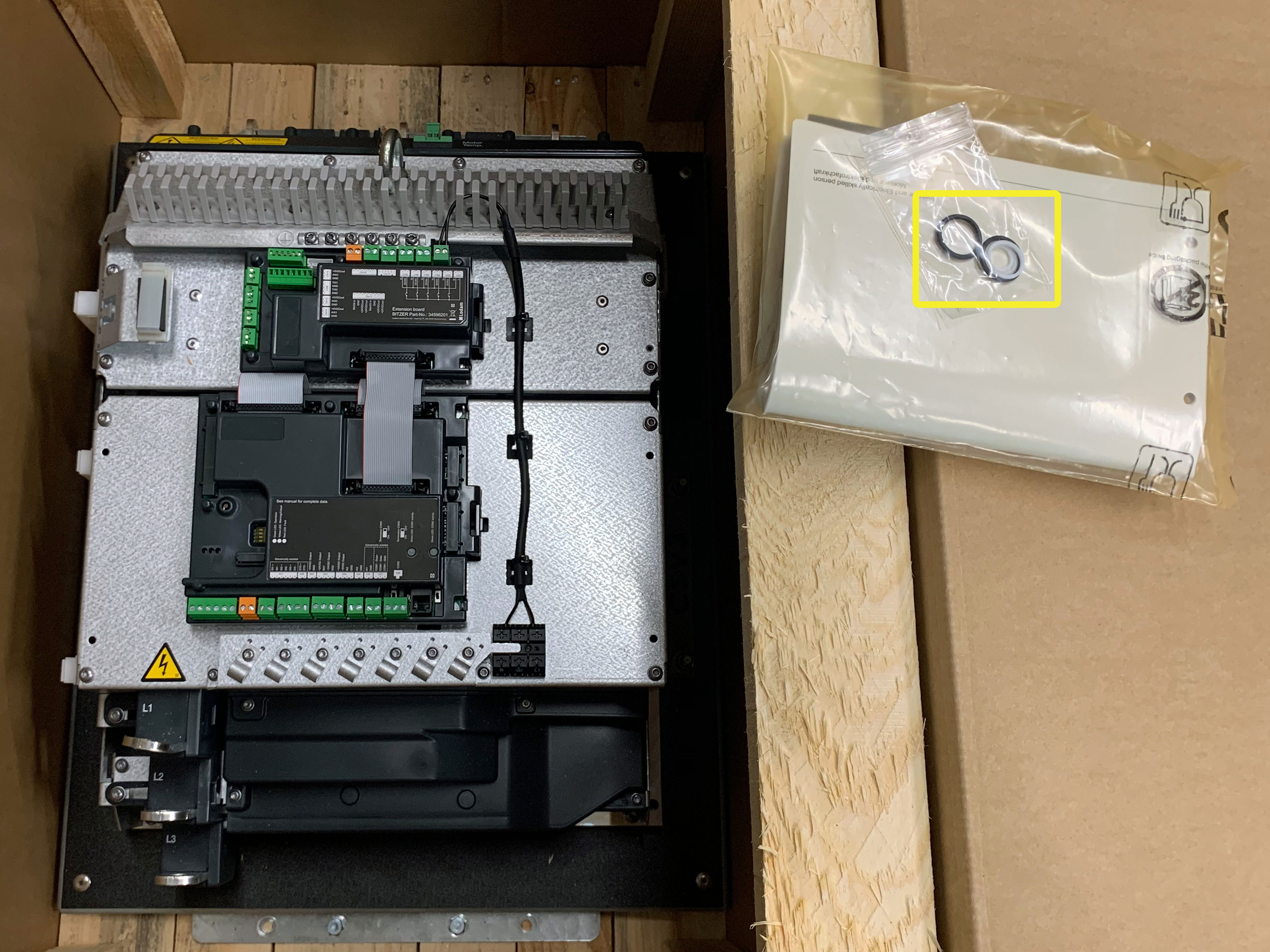
Insert 2 black O-rings on back of flange of the electronic cooling unit valve group
Screw in electronic cooling unit valve group by hand at upper and lower joints
Make sure the that the 2 O-rings on back of the flange stay in position!
Attach flange
- 6 mm hexagon spanner with ball head + extension
Mount flange with torque spanner
- 6 mm hexagon spanner with ball head + extension
- Torque spanner
- Tightening torque: 23 Nm
Risk of damage to the component.
Tighten screws crosswise in at least 2 steps to the prescribed tightening torque.
Mount electronic cooling unit valve group
- One joint at upper electronic expansion valve:
- Spanner SW 22 (counterhold with SW 19 spanner)
- Tightening torque: 50 Nm
- Two joints at lower shut-off valve:
- Spanner SW 30 (counterhold with SW 22 spanner)
- Tightening torque: 85Nm
Terminal assignment at the extension board after the electronic cooling unit valve group has been mounted
- Reconnect all cables and components of the electronic cooling unit valve group.
- Reconnect all terminals and screw the cable cores of the temperature sensor to terminal CN8.
- For detailed description see video mounting instructions SW-164.
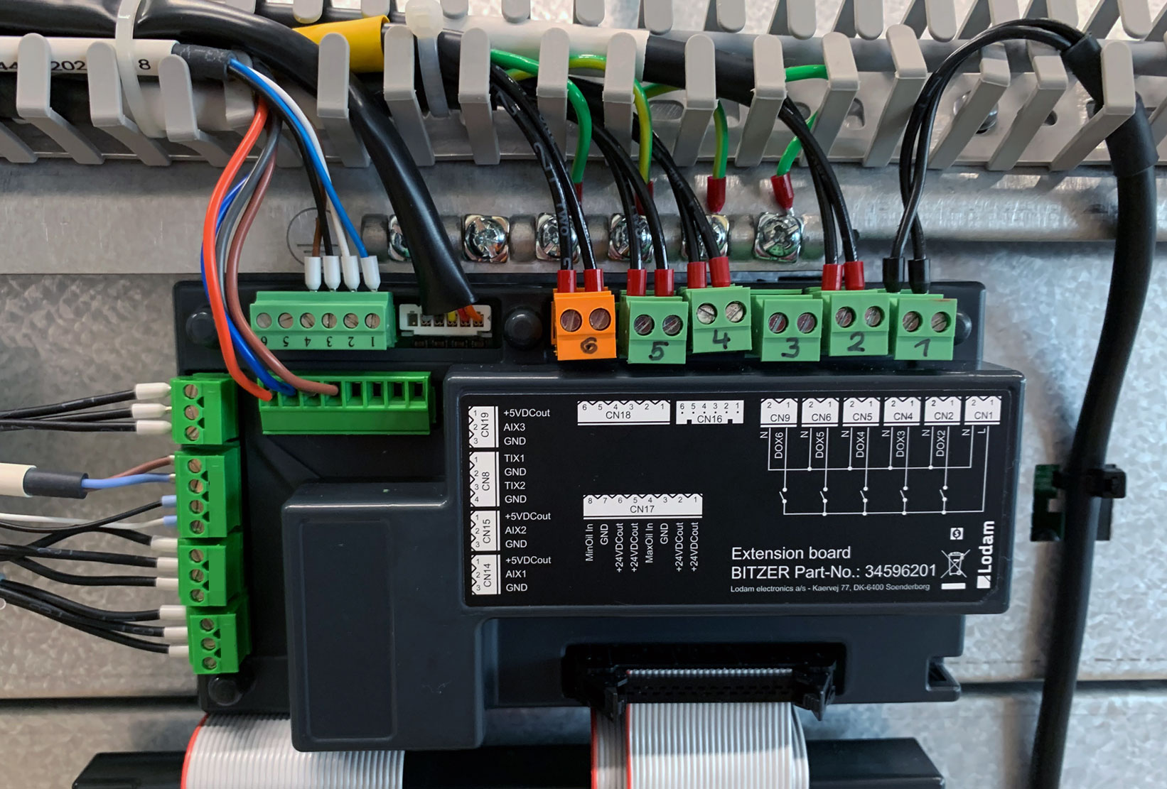
Terminal | Connected component |
|---|---|
CN1 | Voltage supply for solenoid valves and oil heater |
CN2 | Oil heater |
CN4 | Liquid injection |
CN5 | Solenoid valve “FI cooling” |
CN6 | Solenoid valve "Vi silder -" |
CN9 | Solenoid valve "Vi slider +" |
CN16 | Coil of electronic expansion valve for cooling plate |
CN18 | Electronic evaporator pressure valve for cooling plate |
CN17 | Oil monitoring OLC-D1-S min (5-8) and max (1-4, not connected in the picture) |
CN19 | Pressure transmitter at cooling plate outlet |
CN8 | Oil temperature sensor (1+2); Temperature sensor at cooling plate outlet (3+4) |
CN15 | Low pressure transmitter |
CN14 | High pressure transmitter |
Final laying and securing of cables
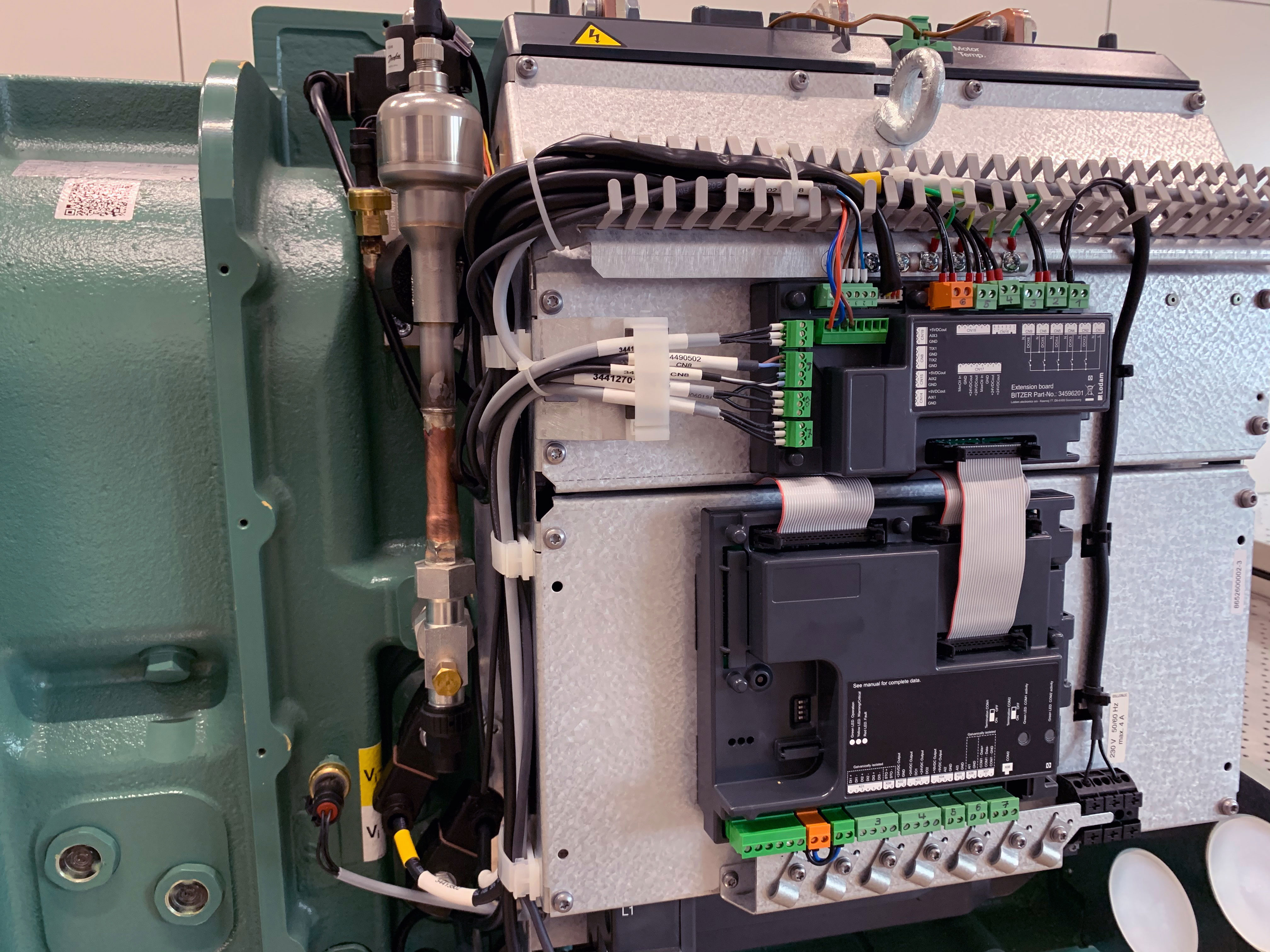
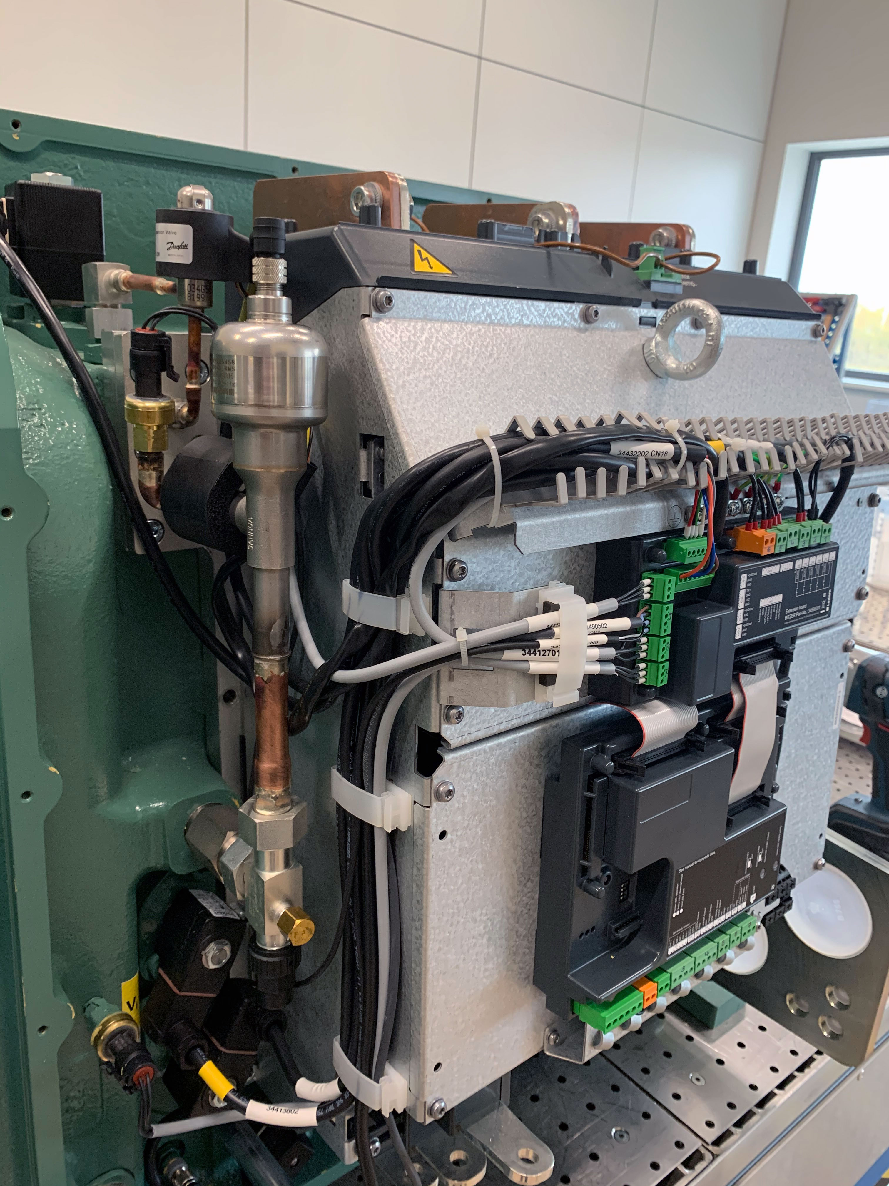
Mounting and electrical connection of the complete electronic cooling unit valve group for FI cooling, see SW-164.