Mount new frequency inverter
Bring frequency inverter into position
- Lifting device to lift/secure the frequency inverter
Slowly bring the FI into position. Push firmly against lower part of housing.
Mount frequency inverter
- Lifting device to lift/secure frequency inverter
- 6 mm hexagon spanner with extension
- Tightening torque: 23 Nm
Remove lifting device
Mount plug of motor temperature sensors
Attach conductor rails
Mount conductor rails with torque spanner
- Spanner SW 17
- 8 mm hexagon spanner to counterhold
- Tightening torque: 56 Nm
- Spanner SW 19
- Tightening torque: 60 Nm
Lay cable and connect terminal CN15 (low pressure transmitter) to extension board
Detailed information about the terminal assignment on the extension board
Screw/connect protective earth conductor and terminals CN2 .. CN9 to extension board
Detailed information about the terminal assignment on the extension board
Lay cable and connect terminal CN17 (oil monitoring OLC-D1-S) to extension board
Detailed information about the terminal assignment on the extension board
Lay cable and connect terminal CN14 (high pressure transmitter) to extension board
Detailed information about the terminal assignment on the extension board
Lay cable and connect terminal CN8 to extension board
Detailed information about the terminal assignment on the extension board
Terminal assignment at the extension board before the electronic cooling unit valve group has been mounted
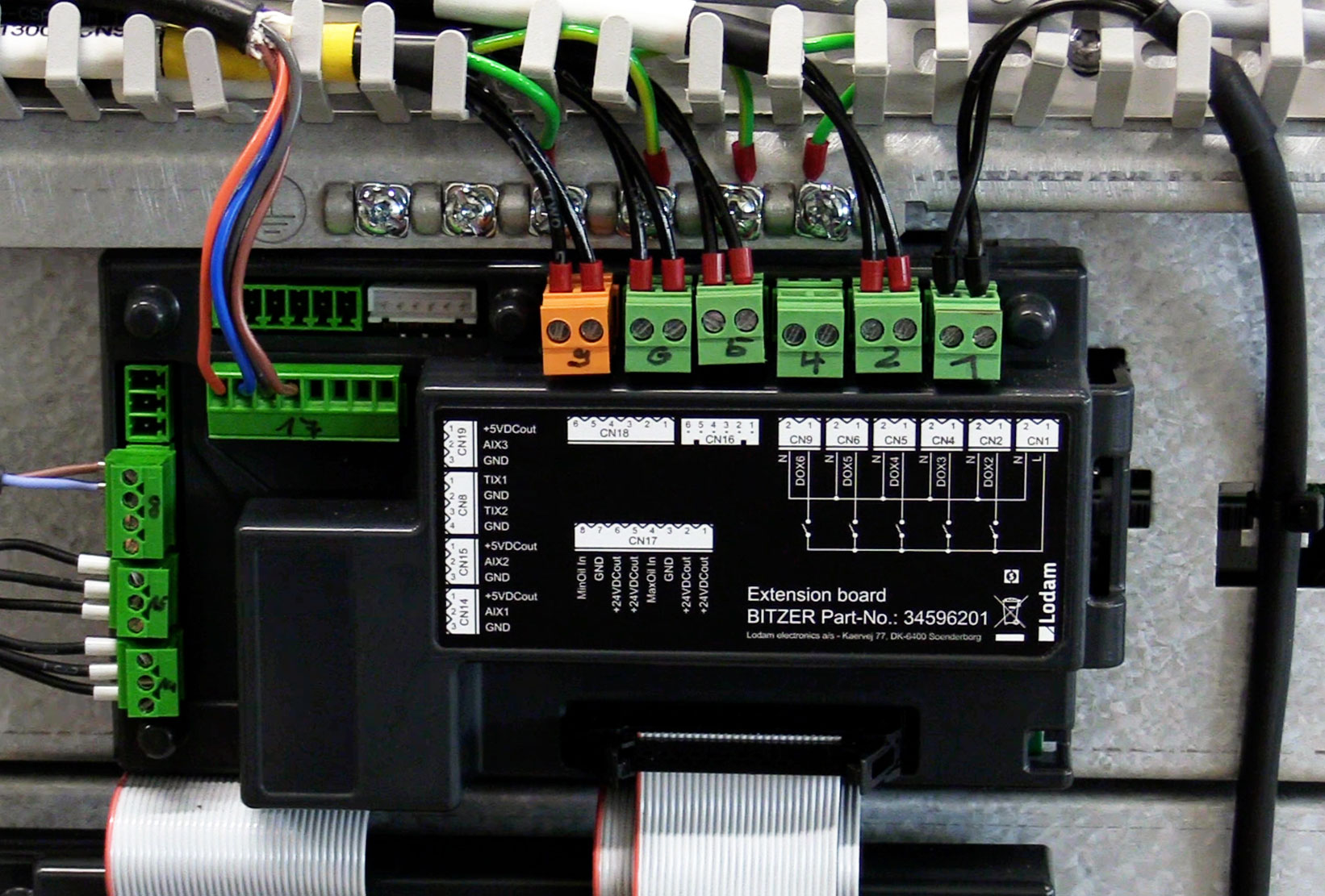
Terminal | Connected component |
|---|---|
CN1 | Voltage supply for solenoid valves and oil heater |
CN2 | Oil heater |
CN4 | Liquid injection |
CN5 | Solenoid valve “FI cooling” |
CN6 | Solenoid valve "Vi silder -" |
CN9 | Solenoid valve "Vi slider +" |
CN17 | Oil monitoring OLC-D1-S min (5-8) and max (1-4, not connected in the picture) |
CN8 | Oil temperature sensor (1+2); Temperature sensor at cooling plate outlet (3+4) |
CN15 | Low pressure transmitter |
CN14 | High pressure transmitter |