Oil separator below compressor level
The safest arrangement: Install the oil separator below the compressor level and lay the discharge gas line with a downward gradient (see following figure). This ensures that oil can drain out of the discharge gas side of the compressor towards the oil separator even during standstill.
Example for HS.53 to 74:
Example for HS.85:
Legend | |
|---|---|
1 | Compressor |
2 | Oil solenoid valve |
3 | Oil flow switch |
4 | Oil filter |
5 | Standstill bypass (if required) |
6 | Oil separator with heating and oil level switch |
7 | Differential pressure valve (if required) |
8 | Water cooled oil cooler (if required) |
9 | Condenser |
10 | Air cooled oil cooler |
11 | Oil pump (if required) |
12 | Mixing valve (if required) |
| Suction gas filter |
| Sight glass |
| Control valve |
| Solenoid valve |
| Check valve |
| Shut-off valve |
PRV | Pressure regulating valve |
LZ | Level monitor |
FZ | Flow limiter |
PC | Pressure-controlled |
TC | Temperature-controlled |

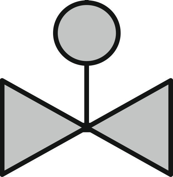
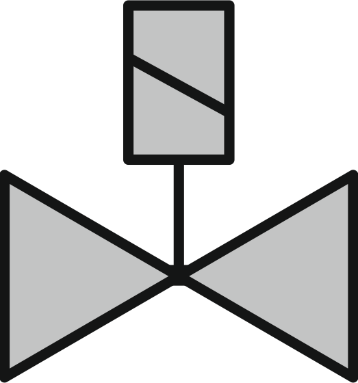
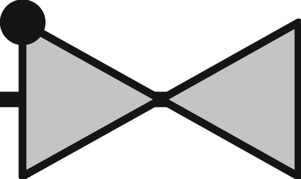

Legend contains connection positions that do not appear in every diagram.
For single compressors, a standstill bypass should also lead from the inlet of the oil separator to the suction side of the compressor. Detailed description: Standstill bypass for oil separator.
Only pipe bends with large radii should be used for oil lines and there should be few deflections. The oil solenoid valve must be close to the injection point and correctly dimensioned. This also applies to the following versions.