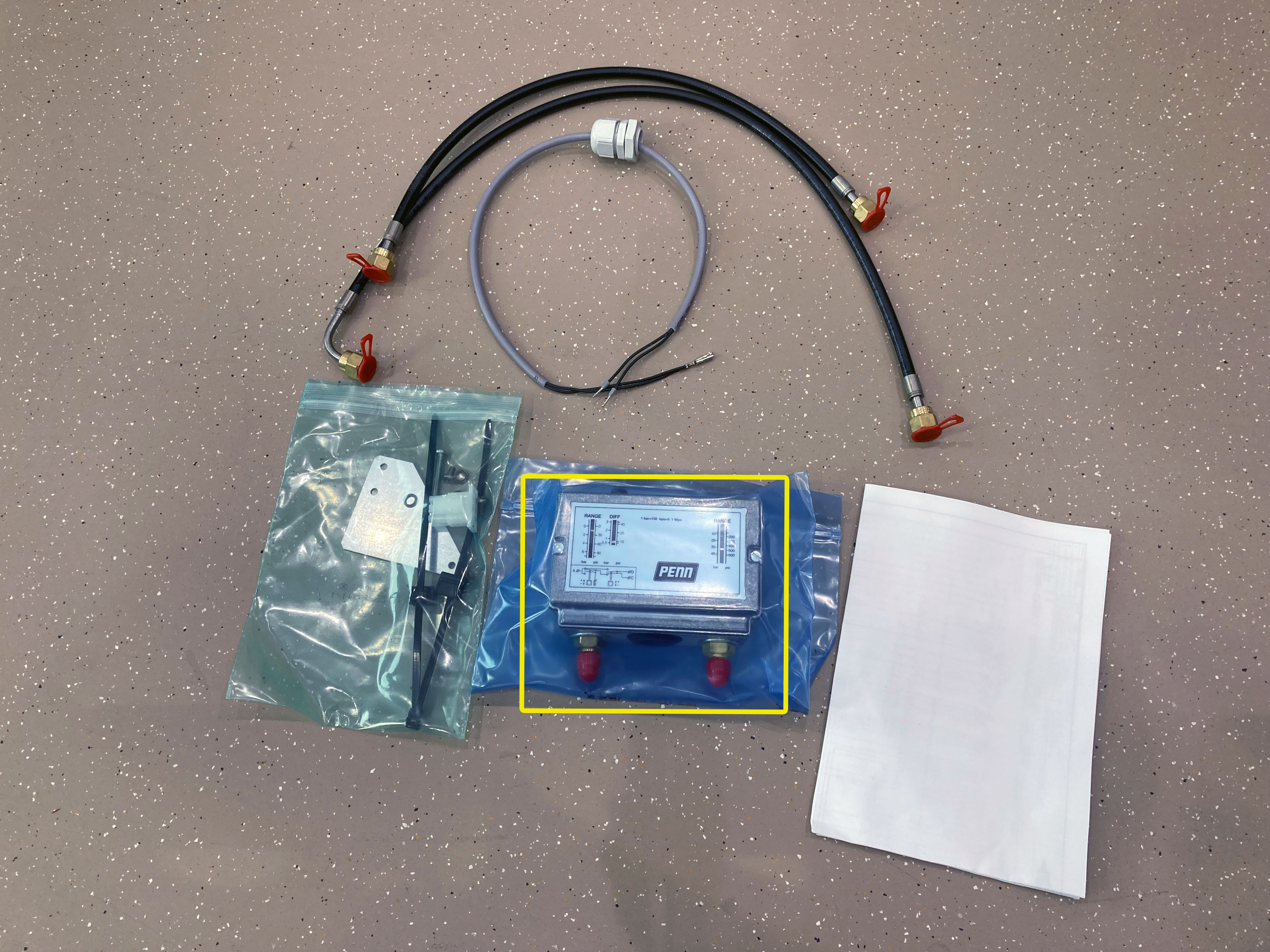
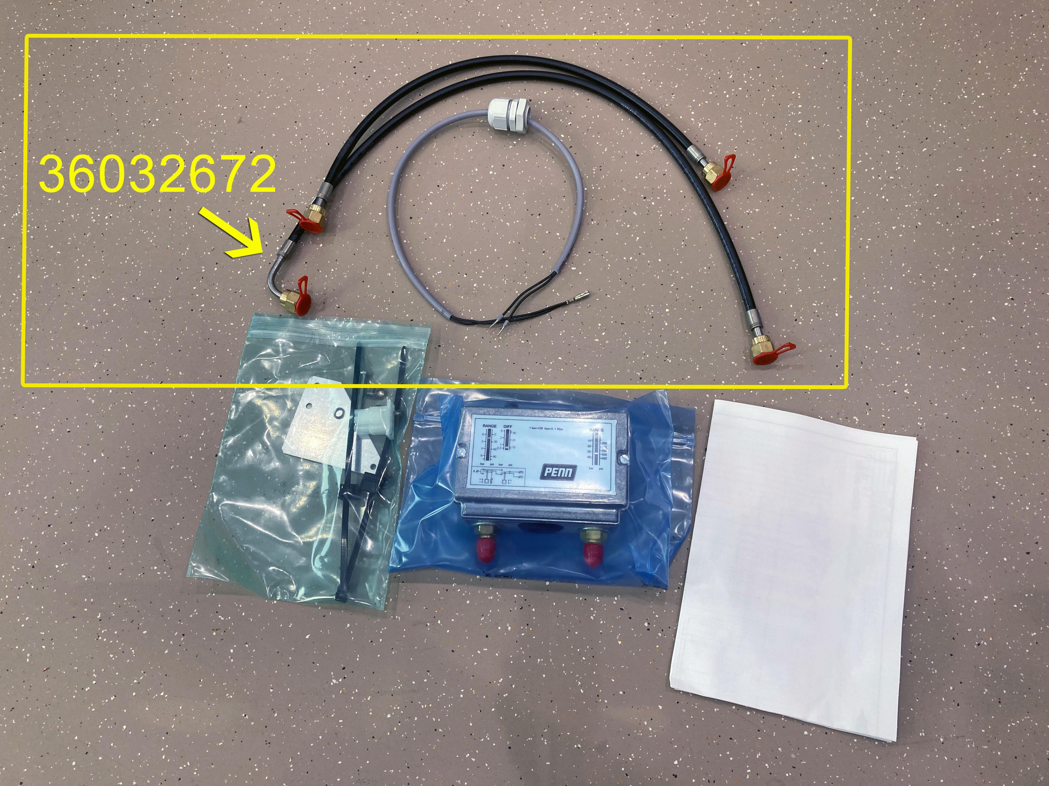
Install new adjustable pressure switch
Connect cable (1) of new adjustable pressure switch to new plug X4
Connect cable (2) of new adjustable pressure switch to new plug X4
Connect oil heater cables (brown and blue) to new plug
Attach new plug X4 to terminal strip
The following 3 steps have to be done only if the terminal box is not already prepared.
Measure hole spacing at mounting plate
- Scale
Plot drill holes on terminal box
- Pencil
- Scale
Drill holes into terminal box
- Drilling machine with 4.5 mm drill bit
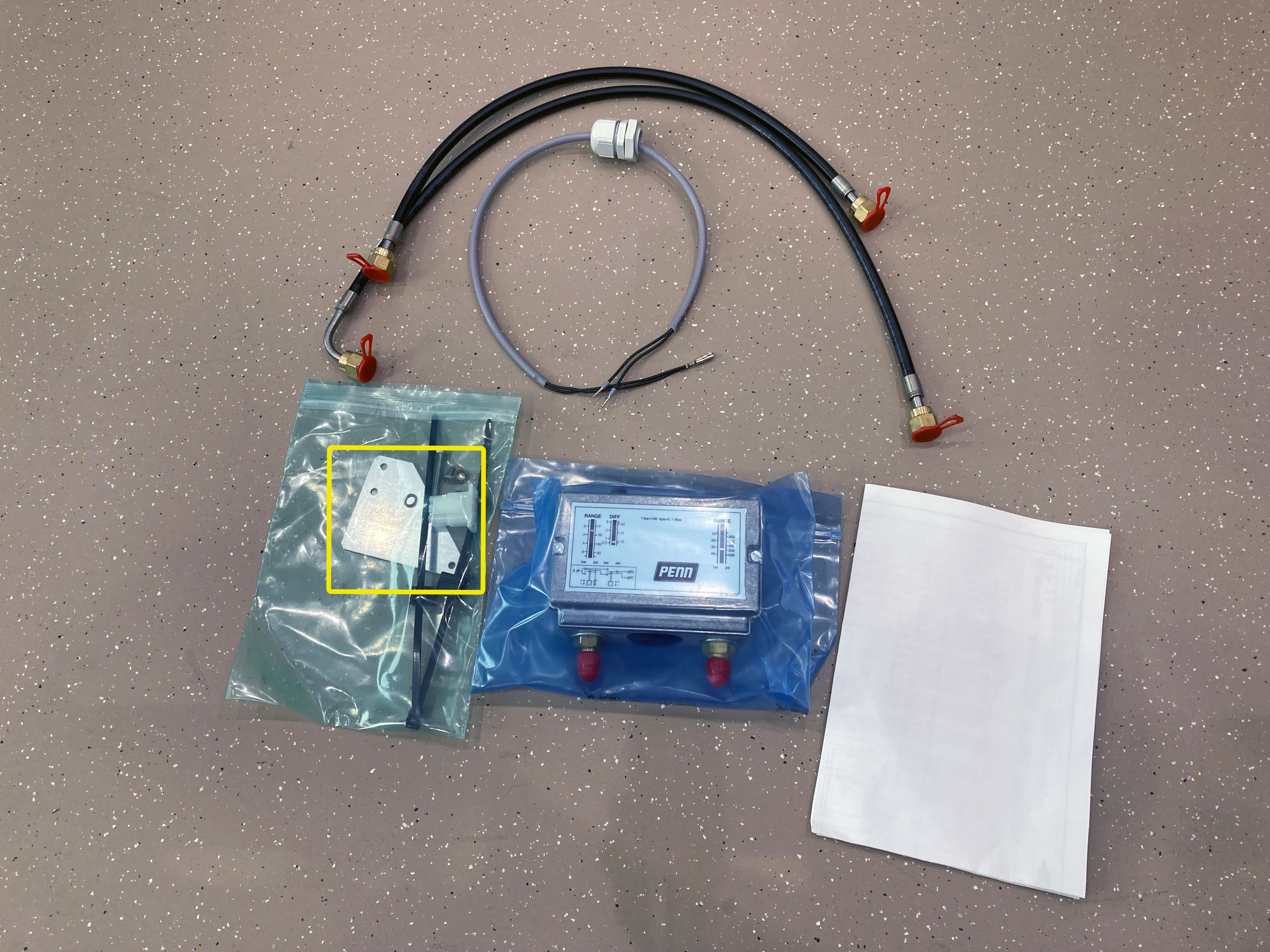
Attach mounting plate to new adjustable pressure switch by using the included screws
Preset cut-out pressures of the new, adjustable pressure switch
High pressure:
- cut-out pressure: 32 bar
- cut-in pressure difference: 4 bar
Low pressure:
- cut-out pressure: -0,3 bar
- cut-in pressure difference: 0,7 bar
- Phillips screwdriver
Remove cover of new adjustable pressure switch
- Phillips screwdriver
Penetrate through-hole in pressure switch
- Phillips screwdriver
Attach new ajustable pressure switch with mounting plate to terminal box
- Phillips screwdriver
- Included screws
Attach new pressure switch with mounting plate to terminal box
- Phlillips screwdriver
- Two M4 nuts (if the terminal box is not already prepared)
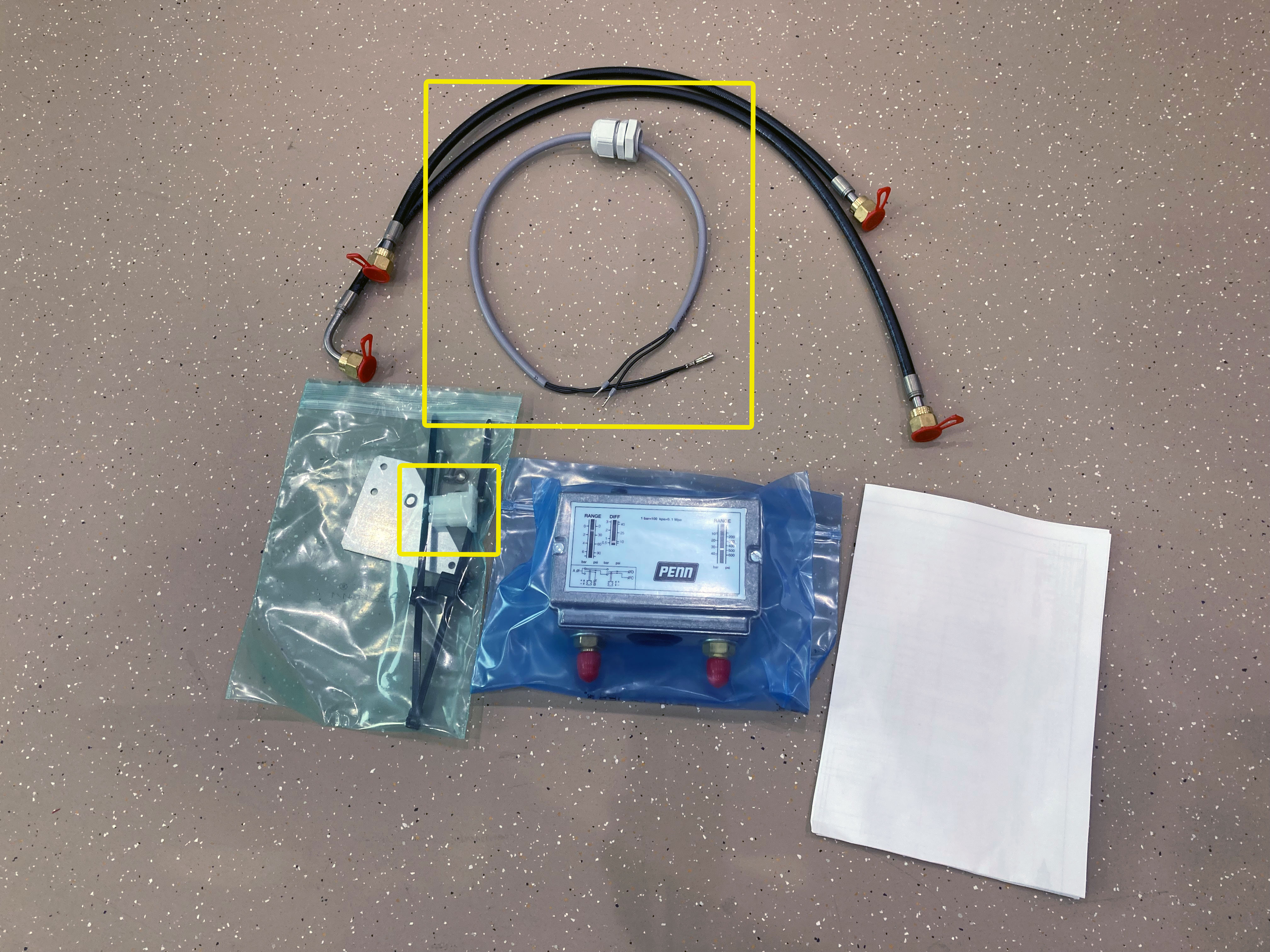
Install cable of new low and high pressure switch, attach screwed cable gland
Connect cable (2) to pressure switch
- Phillips screwdriver
Connect cable (1) to pressure switch and close black cover
- Needle nose pliers
- Phillips screwdriver
Attach cover of new adjustable pressure switch
- Phillips screwdriver
Attach capillary hose with copper gasket to low pressure side of new pressure switch
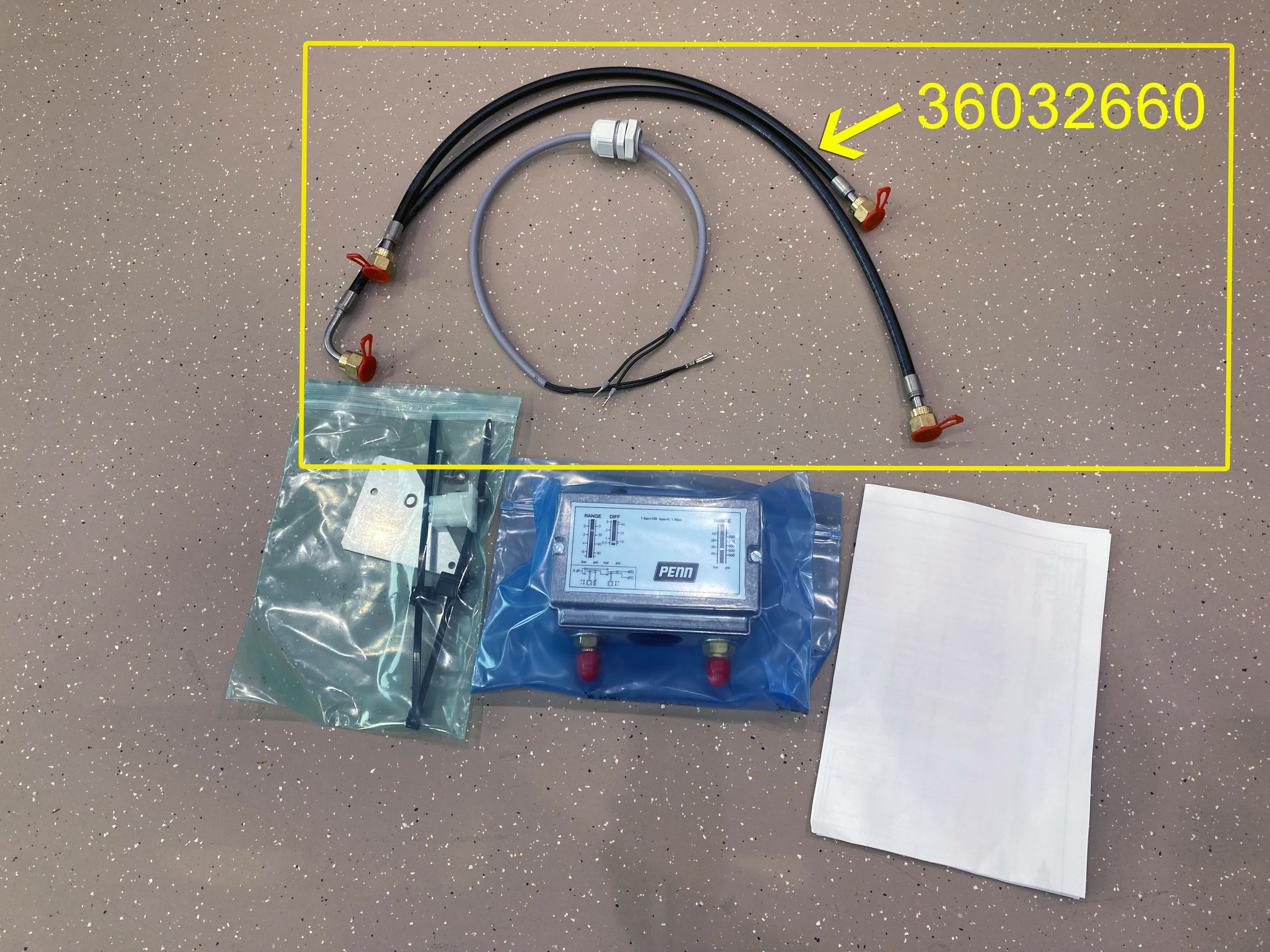
Attach capillary hose with copper gasket to high pressure side of new pressure switch
Attach capillary hose with copper gasket to low pressure switch connection of compressor
LHL3E
The LHL3E condensing units contain 2 cylinder compressors (2EES .. 2CES) instead of 4 cylinder compressors as shown in the video. The positions of the low and high pressure switches differ:
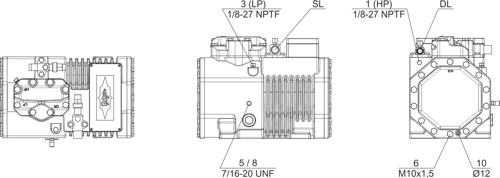
1 (HP) | Connection for high pressure switch (HP) | 3 (LP) | Connection for low pressure switch (LP) |
Attach capillary hose with copper gasket to high pressure switch connection of compressor
LHL3E
The LHL3E condensing units contain 2 cylinder compressors (2EES .. 2CES) instead of 4 cylinder compressors as shown in the video. The positions of the low and high pressure switches differ:
1 (HP) | Connection for high pressure switch (HP) | 3 (LP) | Connection for low pressure switch (LP) |
Mount capillary hoses to compressor
- High pressure switch connection: Spanners SW 16 and SW 13 to counter-hold
- Low pressure switch connection: Spaners SW 16 and SW 12 (or open-ended spanner) to counter-hold
- Open-ended spanner
Mount capillary hoses to new pressure switch
- Spanners SW 16 and SW 17 to counter-hold
Attach cable ties
- Cable ties
Close cable duct
Attach lateral housing plate
- 4 mm hexagon spanner