Selection of compressor and accessory
Compressor selection and capacity grading
For the design of parallel compounding, the required power must be exactly evaluated:
- Power demand at maximum load (design conditions)
- Power demand at minimum load (operation at night, operation outside opening hours, for example in supermarkets, reduced cooling demand and low condensing temperatures at low outdoor temperatures, ...)
- Number of simultaneously operated evaporators
Since each evaporator can have a different effect on the overall load, it may be necessary to weight the individual loads as to how much they contribute to the overall load during a certain operating period. Intelligent control can, however, distribute the load such that the cooling demand does not undergo a drastic change.
The best control accuracy is achieved by having the compound cover the cooling demand by means of a quasi-stepless variation of the cooling capacity between minimum and maximum. A low control range and significant changes in load or capacity result in instability of the overall system. Compressors with variable speed or finely graduated mechanical capacity control (e.g. CRII) are a good option for achieving stable process control, if the control range of at least one compressor can cover the capacity gaps caused by other compressors during switch-on and switch-off.
VsC: Compressor with variable speed
FsC: Compressor with fixed speed
CF: Control accuracy in %
For further information on the optimized selection of compressors and their capacity control, see "ASERCOM Guidelines for the design of multiple compressor racks using frequency inverters" (chapter 2).
Multiple stage systems
Capacity regulation is essential for modern refrigeration systems, especially for refrigerants with high suction densities and volumetric cooling capacities. The targets are:
- covering low minimum load, preferably without on-off cycling
- a high control accuracy (control factor CF) with minimum changes in capacity per step
- cost reduction, e.g. by higher capacity with a lower number of compressors
- minimized diversity of used compressor types
- operational safety
The opposing demands sometimes lead to load conditions with many on-off cycles and unstable (fluctuating) operating conditions by pour control factors. This may lead to reduced efficiency, wet operation, oscillating control circuit, unfavourable operating conditions for compressors, poor temperature control and product quality.
Supplementing the above example of a single-stage refrigeration system, it may therefore be helpful to calculate the control accuracy of a multi-stage refrigeration system (medium and low temperature application) using the following method. It takes into account the industry trend of using fewer and fewer compressors per suction group or temperature stage, and it is intended to combine the opposing demands: high control factor, covering minimum loads and evaluation for the entire system. This is achieved by separately evaluating the low temperature (LT) stage and the minimum load of the medium temperature (MT) stage.
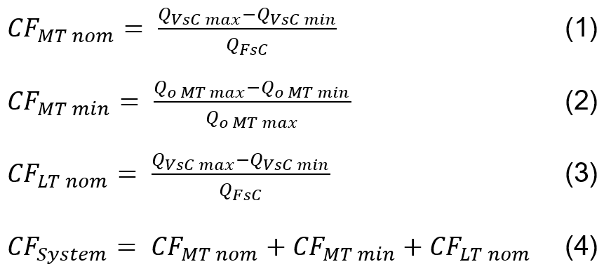
QVsC max: refrigerating capacity of the variable speed compressor at maximum speed
QVsC min: refrigerating capacity of the variable speed compressor at minimum speed
QFsC: Minimum refrigerating capacity of the fixed speed compressor (taking capacity control into consideration if fitted)
nom: nominal capacity at design conditions
min: minimum capacity at design conditions
In a first step (formulas 1 and 3), the control factors are calculated for the MT and LT stage as described in the ASERCOM Guideline.
In addition, formula 2 calculates the ability to cover the minimum load of the MT stage. For this purpose, standard conditions without LT load are assumed (i.e. only normal cooling, the compressor of the LT stage is mathematically switched off).
In the last step (formula 4), CFSystem is calculated as the sum of the individual CF.
The final evaluation distinguishes 5 categories of the control factor CF:
Control factor CF | Evaluation |
|---|---|
CF ≥ 3 | excellent |
3 > CF ≥ 2,5 | good |
2,5 > CF ≥ 1,95 | acceptable |
1,95 > CF ≥ 1,55 | poor |
CF < 1,55 | unacceptable |
This calculation of CF is also applicable if none of the compressors is capacity controlled. In this case, the term in question has a value of zero, which significantly reduces the overall CFsystem.
Tandem compressors
A tandem compressor is the simplest version of parallel compounding of two compressors. The common high-volume suction chamber usually guarantees uniform oil distribution. However, for optimum oil balance and a long lifetime, in general a control with automatic load sequence switching should be provided, which also guarantees a sufficient minimum running time of the two compressors. Short-term operation increases oil carry over and reduces the lifetime.
A finely graduated power adjustment can be obtained by switching the two compressors on and off in combination with capacity regulators (blocked suction ‒ CRII). Speed control of (only) one compressor side is an alternative. Here, too, load sequence switching is recommended, in which the frequency inverter should be assigned alternately to the lead compressor by means of electrical control switch-over.
Additional cooling
In compound systems, compressors and condensers are frequently installed separately from one another. This is why, depending on conditions, additional cooling may be necessary (see application limits) ‒ either by means of
- air (additional fan)
- and / or electronically controlled refrigerant injection (RI)
- or water (water-cooled cylinder heads for compressors 4JE .. 4FE, 6JE .. 6FE).
When a compressor is shut off, its additional cooling must also be shut off in each case. With a fan, this is done by simply coupling the compressor and fan contactor. When using the electronic compressor module CM-RC, the auxiliary fan is controlled according to the discharge gas temperature if required. A solenoid valve that shuts off the water flow when the compressor is at standstill must be connected upstream of the water-cooled cylinder head. Continuously switched-on additional cooling increases the risk of refrigerant condensation in the cylinder head and reduces the effect of the oil heater. This can lead to a high concentration of refrigerant in the oil.