Parallel compounding with oil level controllers
Oil level controllers (with oil separator and oil reservoir) are for universal use. They should be given preference in the following applications:
- Parallel connection of > 3 compressors
- Compressors of different capacities and / or with capacity control (including speed-controlled compressors)
- Parallel connection of compressors operated at different suction pressures
- Systems which tend to migrate large amounts of oil to the low pressure side (e.g. low flow velocity at part load; critical limit depends on the operating conditions and the refrigerant)
- Branched systems with long lines and large amounts of refrigerant
- Compressors of different capacities and / or different lubrication systems (centrifugal lubrication / pump lubrication)
- R744 compressors (sub- and transcritical applications, systems with parallel compression)
The oil level in the compressor is actively monitored and topped up when required. There are different designs:
- Mechanical oil level controllers with a combination of float and valve systems
- Electronic oil level controllers with float or sensor technology (e.g.: Oil level controller OLM-IQ). The oil supply is controlled indirectly via an integrated or external solenoid valve. This version simultaneously allows minimum level monitoring of the oil level and should therefore be given preference.
Oil level controllers are mounted along with the relevant adaptors directly on the sight glass connection; in doing so, the available sight glass is removed (Parallel compounding with oil level controllers).
General requirements and recommendations
Systems equipped with oil level controllers require an oil separator that provides the oil to be distributed. In general, a common oil separator is used (Parallel compounding with optimized suction header).
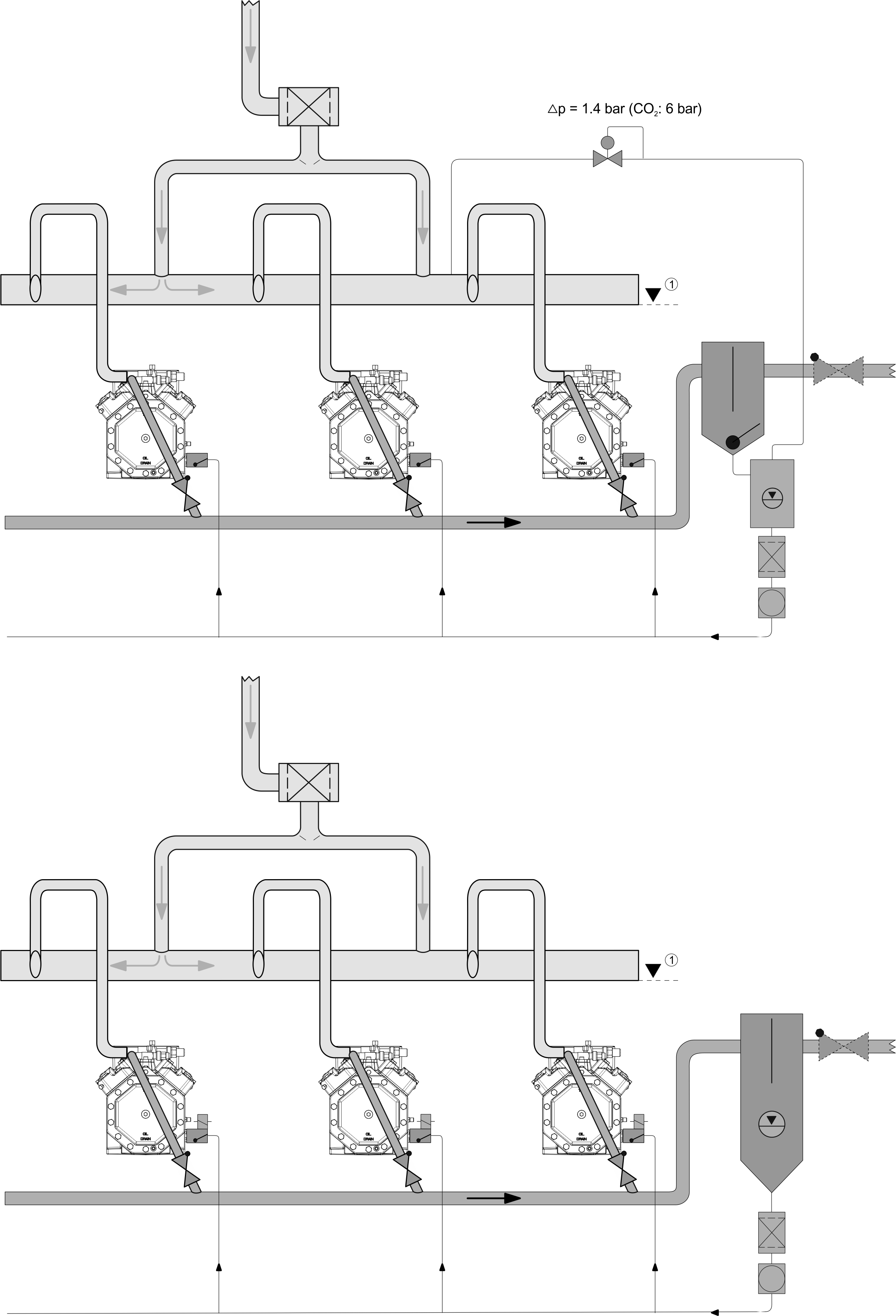
①: The suction header can also be arranged below the compressor level
The oil distribution to the compressors (controllers) takes place from an oil tank. It must have a minimum volume to compensate for variations in the oil balance (design according to manufacturer’s specifications). Two versions are on offer:
Low-pressure reservoir as a separate vessel (Fig. above, top half)
- The oil from the separator is fed into the tank under high pressure. There, a controlled pressure reduction takes place via a degassing line to the suction header. A differential pressure valve (1.4 bar) in the connecting line ensures sufficient excess pressure upstream of the oil level controller for "standard refrigerants".
- In 2-stage compressors, the crankcases are under intermediate pressure. The degassing line must therefore for routed to a transverse connecting line between the connections at the motor case cover (see dimensional drawings in Operating instructions KB-150 or Bitzer Software) – level of the connecting line below the connecting position.
Mechanical oil level controllers may only be suitable for relatively small pressure differences!
Select a design for a working pressure of at least 6.5 bar.
- Systems for transcritical operation with R744 require oil separators with coalescence filter cartridges. The oil separators must not be equipped with a float valve. If necessary, the (electronic / optical) level monitoring in the oil separator opens a solenoid valve in the line to the oil tank. The volume of the oil tank must be twice as large as the entire oil volume of the compressors. The pressure in the tank must be higher than the highest suction pressure in the system so that the oil can flow back into the compressors. Degassing is therefore routed into the corresponding suction gas line.
In systems with parallel compression, degassing always takes place at intermediate pressure level and not, for example, at the suction pressure level of compressors for medium temperature application. In the degassing line, discharge gas valves must preferably be used. The required pressure difference depends on the boundary conditions, pressure differences between 2.5 and 4.5 bar are normally necessary.
In so-called booster systems, the low pressure compressors are supplied with oil from the common tank. This can result in the excess pressure upstream of the oil level controller being clearly higher than the values permitted for mechanical controllers. This is why, in general, only electronic oil level controllers equipped with integrated solenoid valves that are suitable for the high differential pressures of R744 systems should be used.
To adjust the oil management, the following points must be observed and harmonized with each other: - Nozzle cross-sections of the oil level controllers used in the respective compressor stage
- Opening times for oil replenishment of the oil level controllers used
- Provided oil volume in the tank
- Nominal maximum pressure difference in the tank
- Length and cross-section of the oil lines from the tank to the oil level controllers
High-pressure reservoir as additional oil reservoir in the lower part of the oil separator (Fig. above, bottom half)
- The oil separator has been designed here without float valve, the oil line leading directly to the oil level controllers.
- Only electronic oil level controllers with integrated solenoid valves are suitable for these systems. They must be suitable for operation with full pressure difference. The nozzles used for limiting the oil flow are adjusted as a function of the pressure difference according to manufacturer’s specifications. This is extremely important because a large amount of refrigerant is dissolved in the oil due to the high upstream pressure. If pressure is subsequently reduced to the level of the crankcase, the refrigerant becomes gaseous again. If the continuous feed rate is too high, considerable foaming will occur, resulting in liquid slugging, increased oil carry over, insufficient oil level control and lack of oil.
Design of oil level controllers and accessories
The volume of the reservoir must be sufficiently large to compensate for different oil circulation rates in the system (e.g. increased oil return from evaporators after defrosting). Oil level controllers, oil reservoirs, differential pressure valves, oil filters (in the feed line to controllers), oil separators and check valves must be designed in accordance with manufacturer’s specifications. In addition, check valves and oil separators are subject to the information given above (check valves, oil separators).
Most BITZER reciprocating compressors have a screwed sight glass with a 1 1/8-18 UNEF connection, for details see the Operating Instructions of the respective compressor. Adaptors for mounting the oil level controllers are supplied by their respective manufacturers.
Suction and pressure headers for use with oil level controllers
Headers and pipes can be designed in accordance with the versions shown above (suction headers, pressure headers). However, suction headers have lower overall symmetry and gas velocity requirements: A lateral suction gas inlet is possible, and several suction line groups can be operated in parallel (e.g. with different suction pressures). For this case, a system with high-pressure reservoir is recommended for "standard refrigerants", in order to guarantee enough oil pressure at the controllers under all operating conditions. However, the pipe sections connected to the compressors should conform to the recommended design.
Danger of liquid slugging!
In parallel compounding with oil level controllers, observe the recommended pipe layout!
Execute the construction such that no oil or refrigerant condensate (from the header) can flow back to the compressor at standstill.
In general, pressure headers and check valves must fulfil the criteria mentioned above (Parallel compounding with optimized suction header).