Pipe layout and components
Use only pipes and system components that are
- clean and dry inside (free from slag, swarf, rust and phosphate coatings) and
- delivered with an air-tight seal.
Risk of compressor damage due to liquid slugging and lack of oil!
Avoid oil or liquid migration into the compressor and oil traps or oil pockets in the system!
- Plan the pipe layout and design of all system components carefully.
- Install the liquid subcooler / intermediate pressure vessel below the compressor.
- Design the pipe layout running vertically upwards before going back down to the ECO suction connection of the compressor.
- Install a suction accumulator upstream of the compressor´s suction gas connection (position SL, Dimensional drawing ORBIT FIT) in systems with a high amount of refrigerant charge.
- Ensure the minimum gas flow velocity for oil return in the system.
Risk of pipe fractures and leakages on compressor and system due to vibrations.
Avoid critical pipe lengths and/or install a muffler.
Reduced system efficiency due to ambient heat gains in the liquid line!
Insulate the liquid line between the liquid subcooler and the expansion valve of the evaporator!
Pipe dimensions for the ECO suction gas line for GED8: 1/2”
For systems with distances > 1 m between the liquid subcooler and the ECO connection at the compressor, one size larger pipe dimensions are recommended!
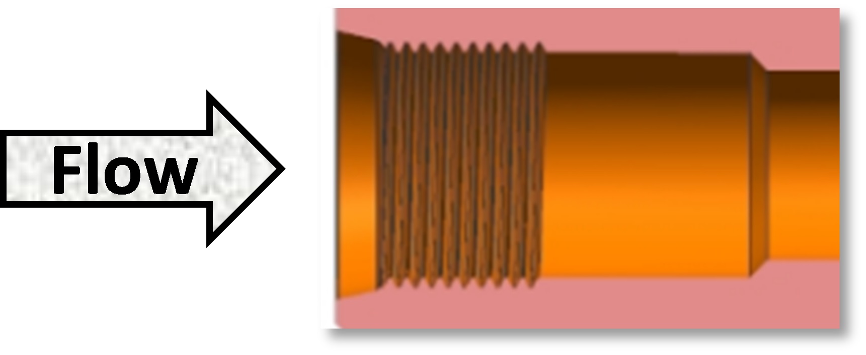
ECO port connection sizes for GED8:
- 9/16-18 SAE O-ring thread
- 3/8 inch (1/2 OD) copper braze
