Outside the terminal box for A3 regrigerants
If the SE-i1 is used with refrigerants classified as A3 (e.g. propane) and A2, it must not be installed inside the terminal box of the compressor
It must be installed outside the terminal box of the compressor, either in an external terminal box (at least IP54), or inside the system's switch cabinet.
Authorized staff
All work done on the products and the systems in which they are or will be installed may only be performed by qualified and authorised staff who have been trained and instructed in all work. The qualification and competence of the qualified staff must correspond to the local regulations and guidelines.
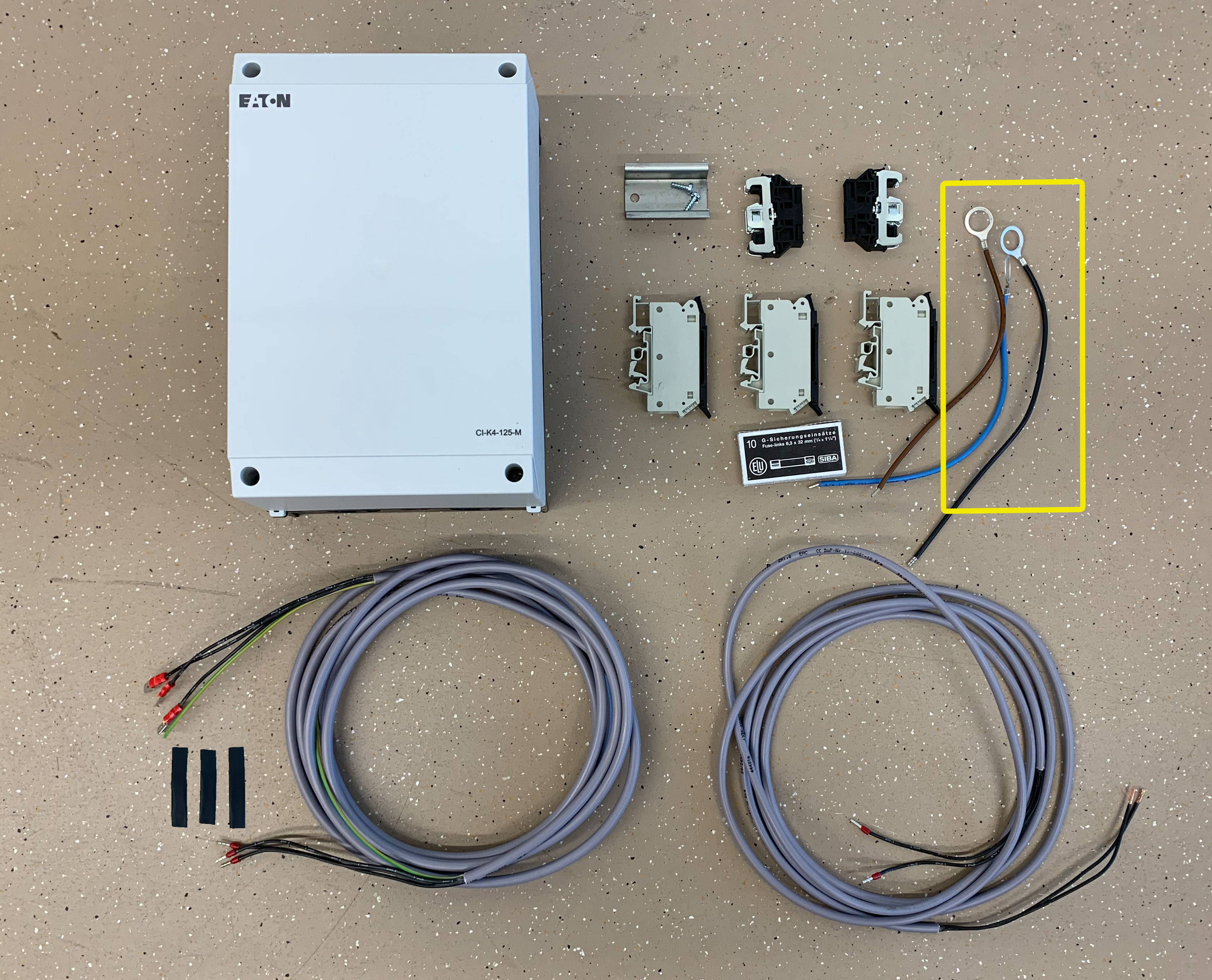
Attach the 3 cables for phase monitoring to motor pins
- Ratchet wrench with socket spanner size 17
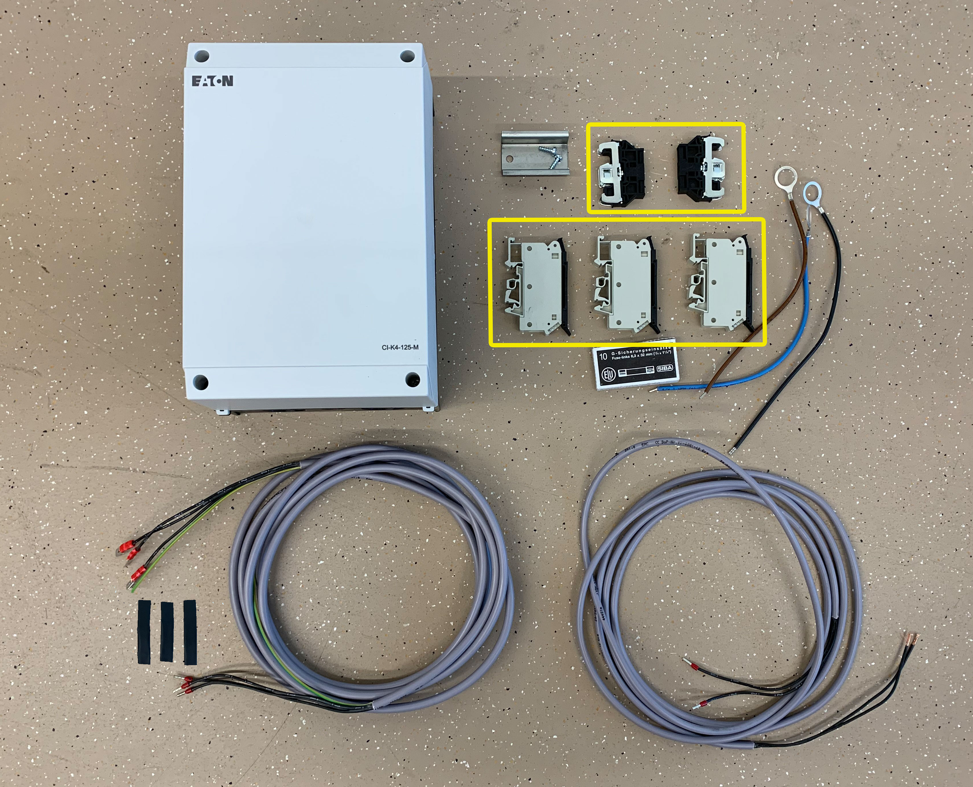
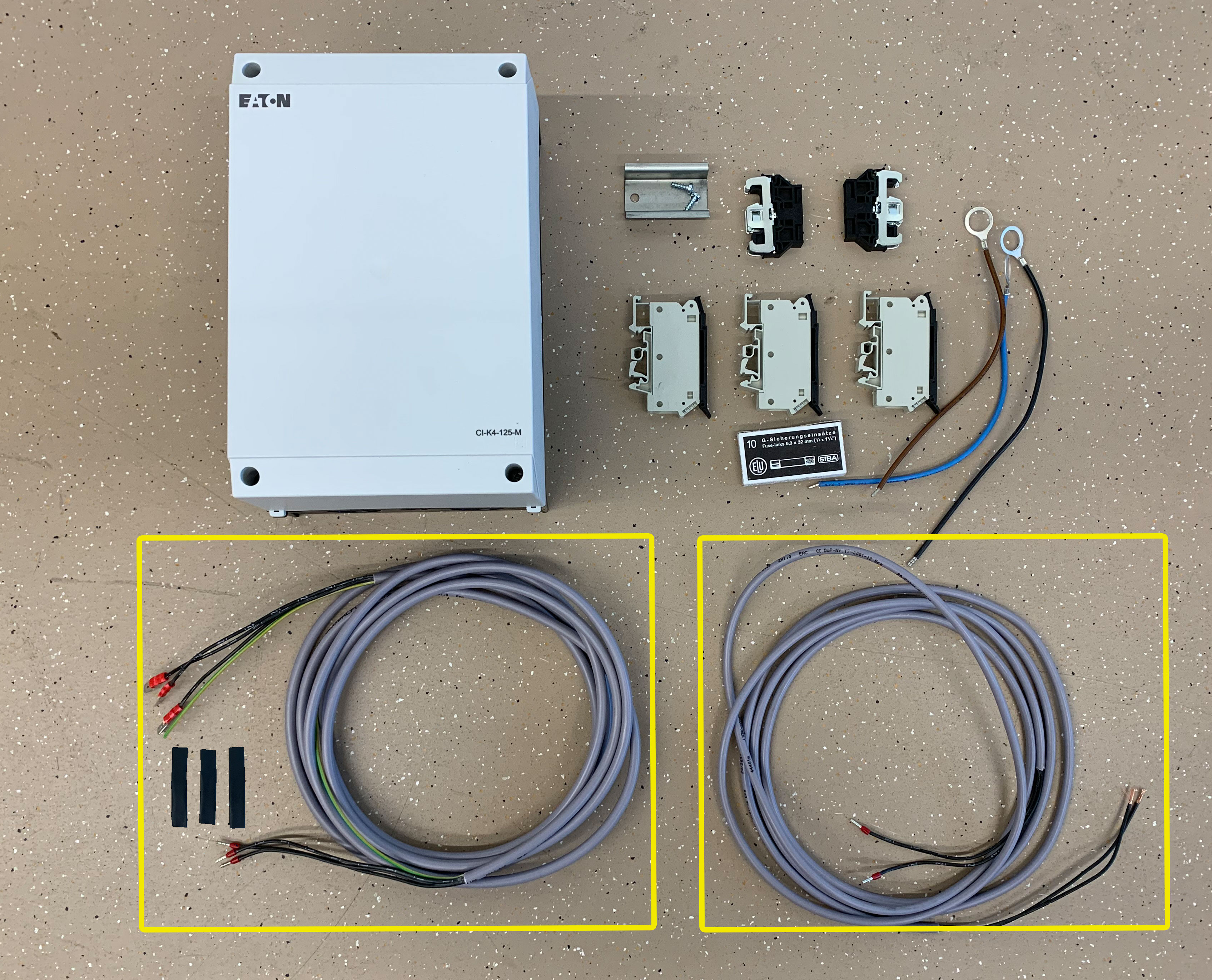
Attach top hat rail
- Phillips screwdriver

Attach fuse terminals and row-end terminals to top hat rail
- Screwdriver
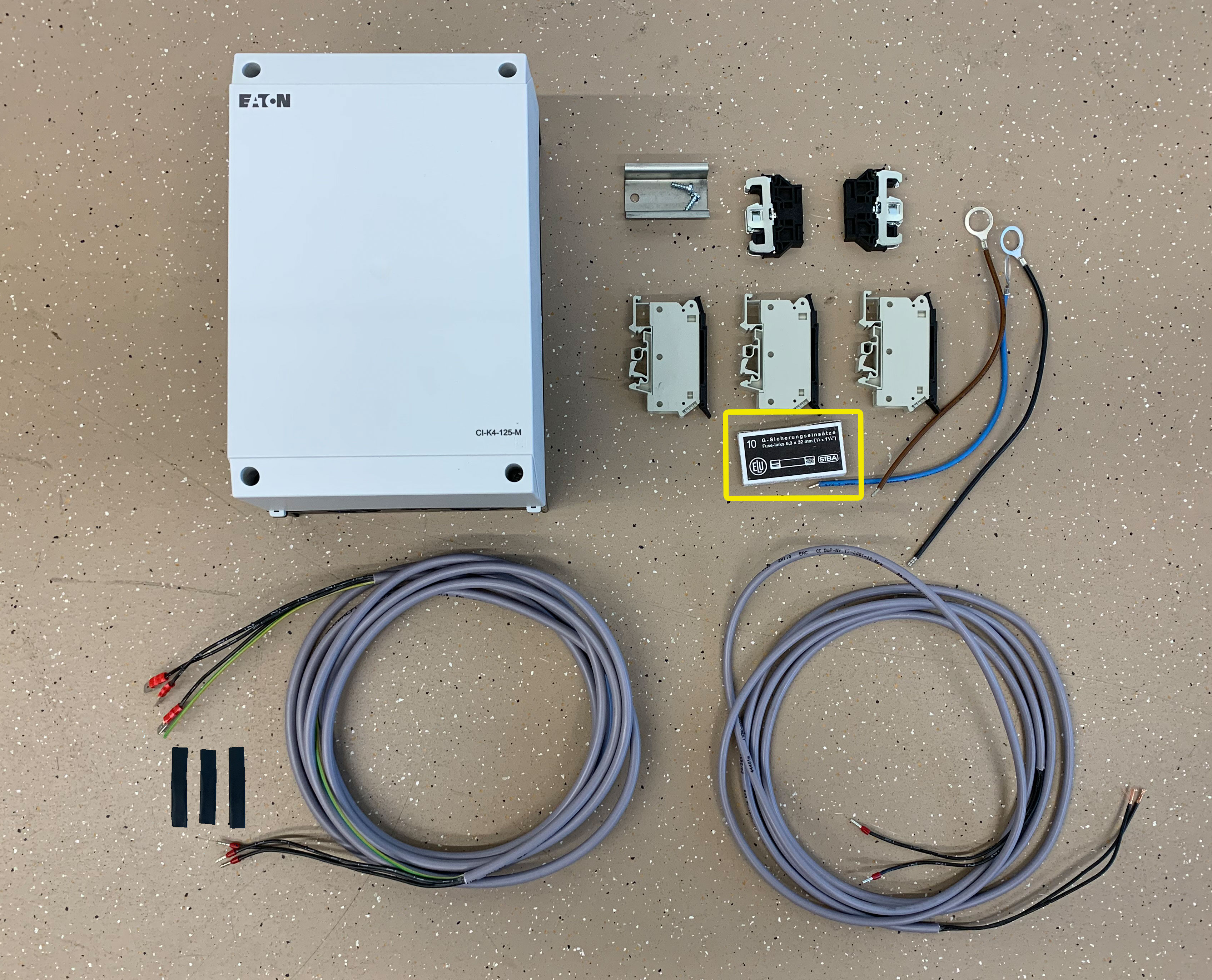
Insert fuses into terminals
Connect the 3 cable cores (black, brown, blue) of phase monitoring to fuse terminals
- Screwdriver
- After mounting, check electrical cable connections for tightness!
Connect cable cores of PTC resistors for monitoring the motor winding temperature to terminals 5 and 6
- Screwdriver
- After mounting, check electrical cable connections for tightness!
Open cable bushing at terminal box
- Screwdriver handle
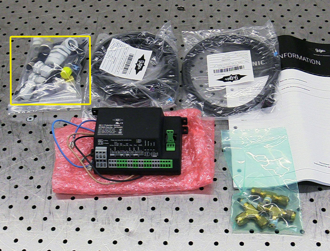
Attach screwed cable glands M20x1,5 and M16x1,5
Guide connecting cable of "Motor PTC" and "Phase monitoring" into terminal box
Maximum admissible cable length for PTC temperature control circuit tested according to UL/EN60335: 10 m
Maximum admissible cable length for PTC temperature control circuit tested according to EN12693: 30 m
Maximum admissible cable length for PTC temperature control circuit tested according to UL/EN60335: 10 m
Cable lengths > 30 m are not tested during type approval!
Connect cable cores of connecting cable of "Phase monitoring" to fuse terminals in terminal box
- Screwdriver
- Cable 1→ black
- Cable 2 → brown
- Cable 3 → blue
- After mounting, check electrical cable connections for tightness!
Connect cable cores of connecting cable of "Motor PTC" to terminals 5 and 6
- Screwdriver
- After mounting, check electrical cable connections for tightness!
Attach terminal box cover
- 5 mm hexagon spanner
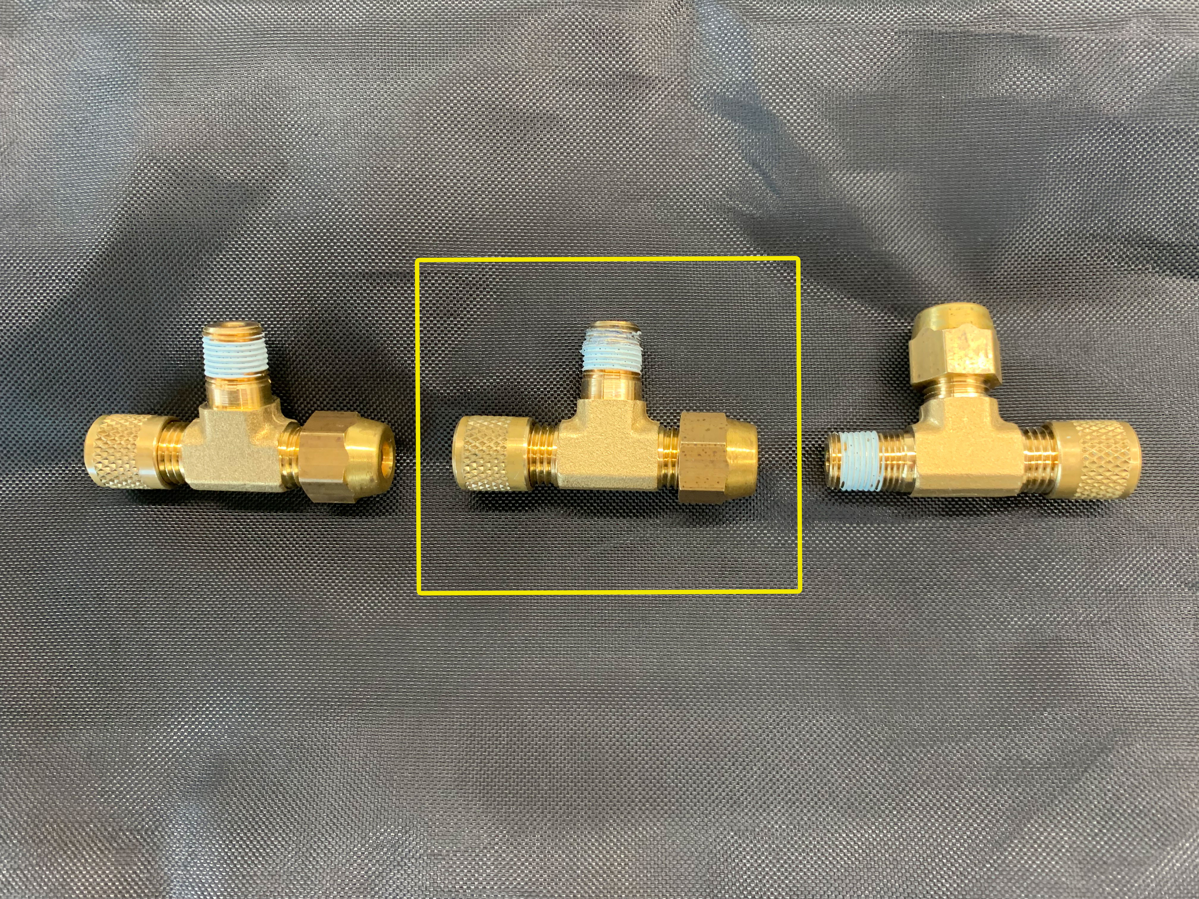
Attach T joint for mounting the high pressure transmitter
- Ring wrench / spanner SW 13
- Spanner SW 14
The connection positions for pressure transmitters at the CS. series vary depending on compressor size. The following videos show the positions for a CS.85 compressor.

Attach T joint for mounting the low pressure transmitter
- Ring wrench / spanner SW 13
- Spanner SW 14
The connection positions for pressure transmitters at the CS. series vary depending on compressor size. The following videos show the positions for a CS.85 compressor.
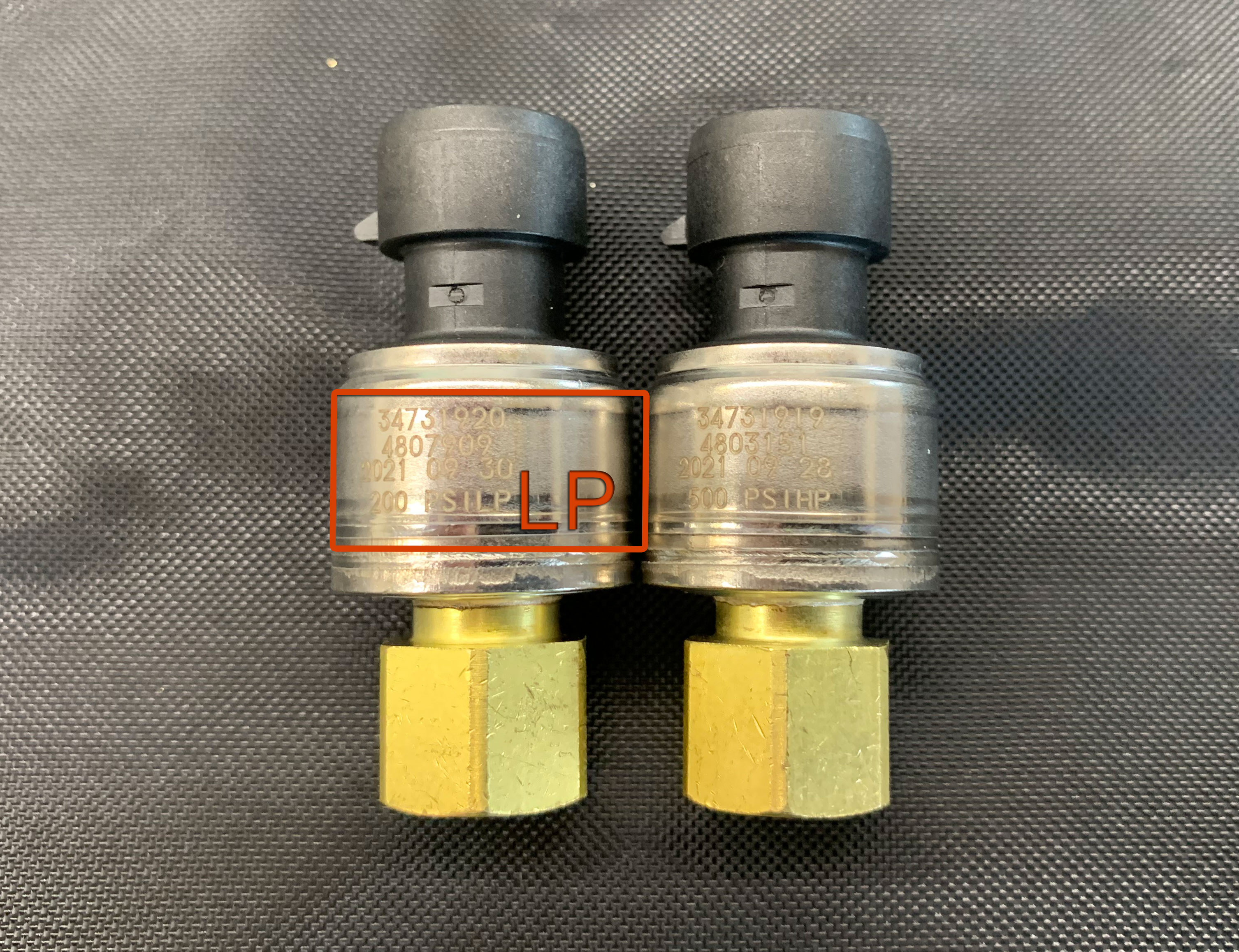
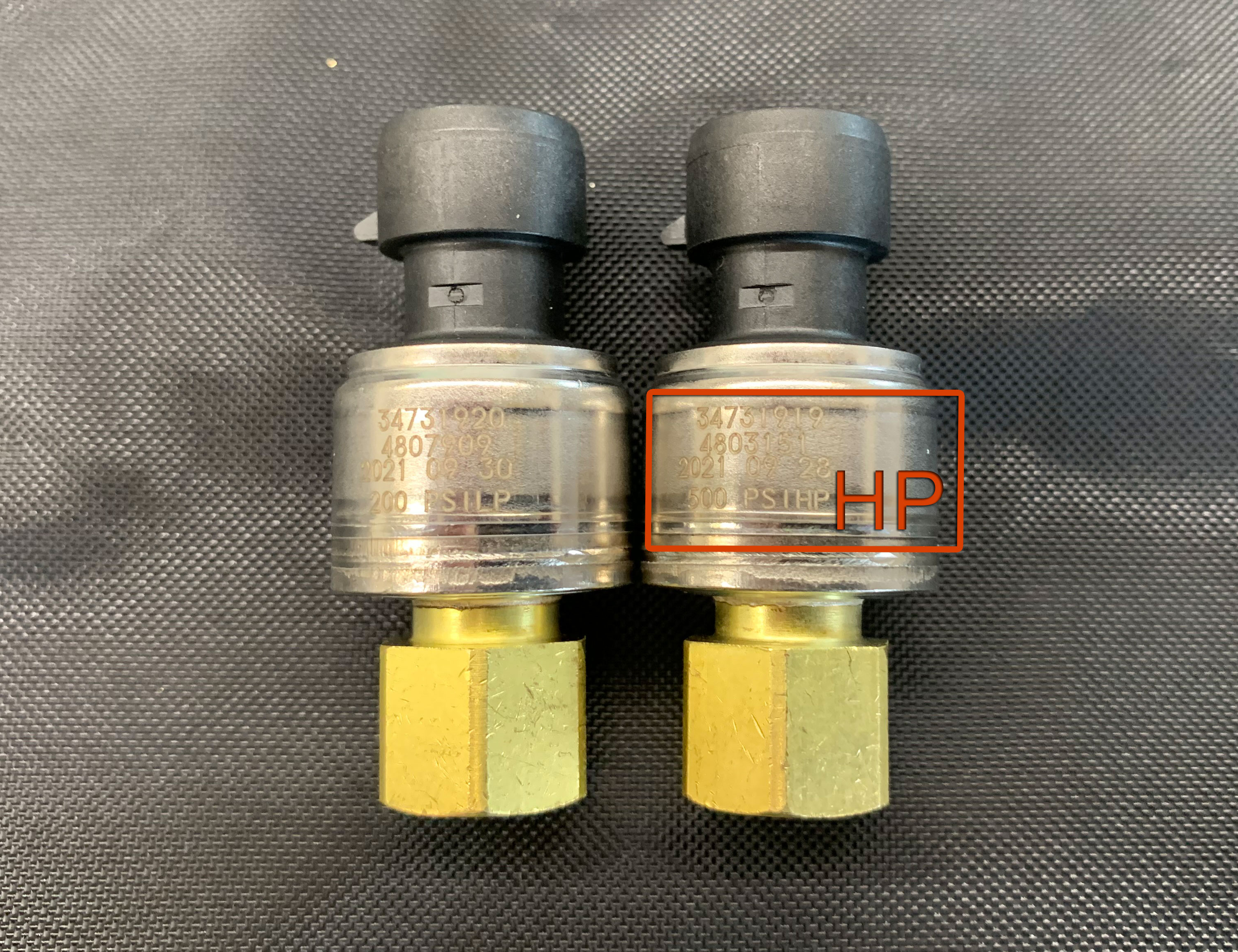
Mount the low pressure transmitter
- Spanner SW 16 (counter-hold with spanner SW 14)
- Suitable refrigeration compressor oil
- Torque spanner
- Tightening torque: 35 Nm
Attach cable of low pressure transmitter

Mount the high pressure transmitter
- Spanner SW 16 (counter-hold with spanner SW 14)
- Suitable refrigeration compressor oil
- Torque spanner
- Tightening torque: 35 Nm
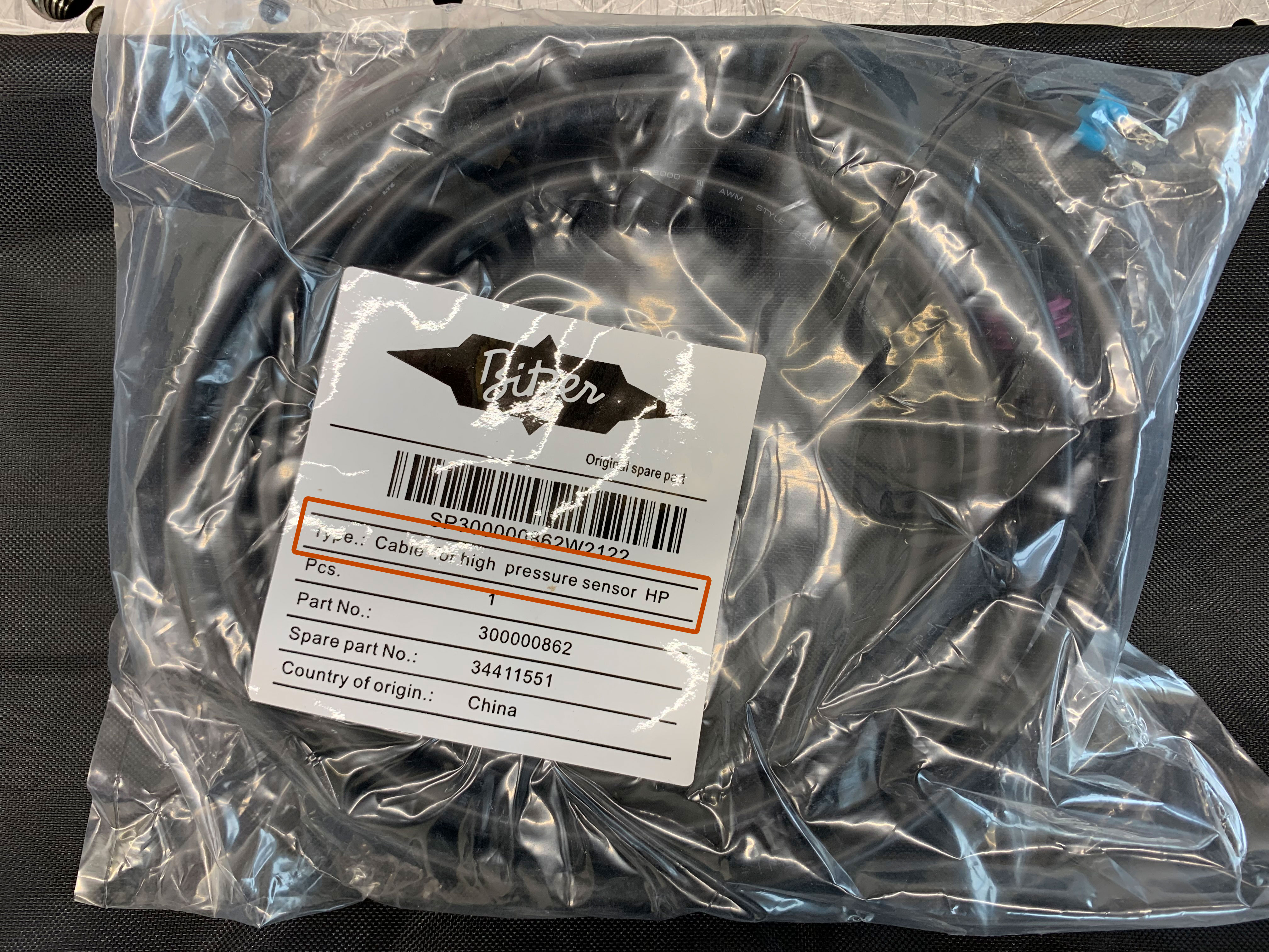
Attach cable of high pressure transmitter
Create a vacuum at the high pressure side (at least -0,5 bar)
This ensures that no oil leaks through the connection when the discharge gas temperature sensor gets replaced.
- Vacuum pump
Remove existing discharge gas temperature sensor (PTC) and install new discharge gas temperature sensor (NTC)
- Work quickly!
- Ratchet wrench with socket spanner size 17

Mount new discharge gas temperature sensor (NTC)
- Ratchet wrench with socket spanner size 17
- Torque spanner
- Tightening torque: 17 Nm
Switch off and remove vacuum pump
Attach cable of new discharge gas temperature sensor (NTC) and screw in by hand
Detach cover of external terminal box
Alternative installation in the system's switch cabinet!
- Phillips scewdriver
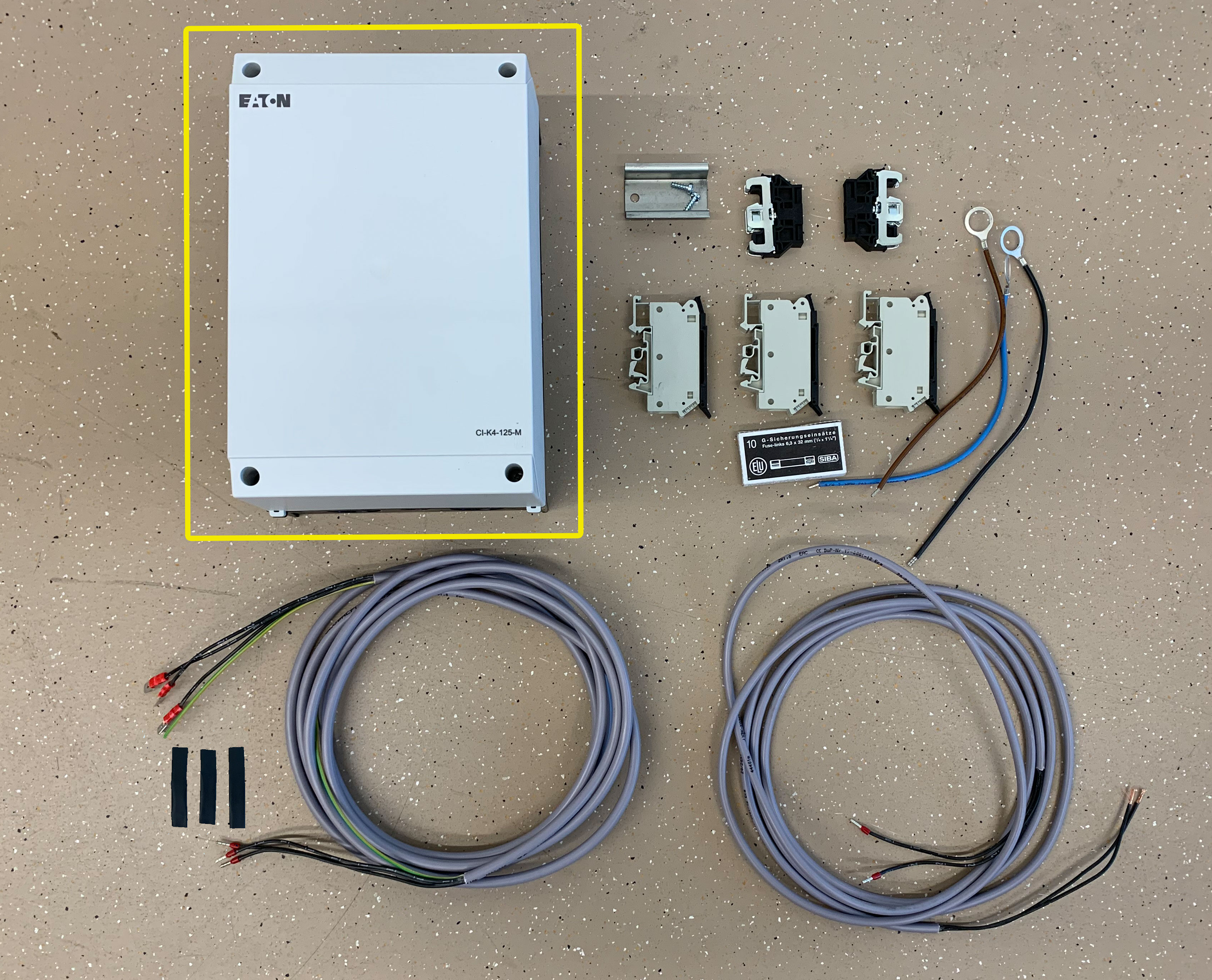
Drill holes (for M4x10 screws) into the assembly panel of the external terminal box to attach the SE-i1
- Drill
- See dimensional drawing for details
Attach SE-i1 with washers, screws (M4x10) and nuts to assembly panel
- Hexagon spanner 5 mm
- Pliers
Open cable bushings at external terminal box
- Screwdriver
Attach suitable screwed cable glands to external terminal box
Mount SE-i1 with assembly panel into external terminal box
- Phillips screwdriver
Guide cable of discharge gas temperature sensor (NTC) into external terminal box
Guide cable of low pressure transmitter into external terminal box
Guide cable of high pressure transmitter into external terminal box
Connect cable cores of discharge temperature sensor (NTC) to terminals 12 and 13 of SE-i1
- Screwdriver
- Brown cable → terminal 12
- White cable → terminal 13
- After mounting, check electrical cable connections for tightness!
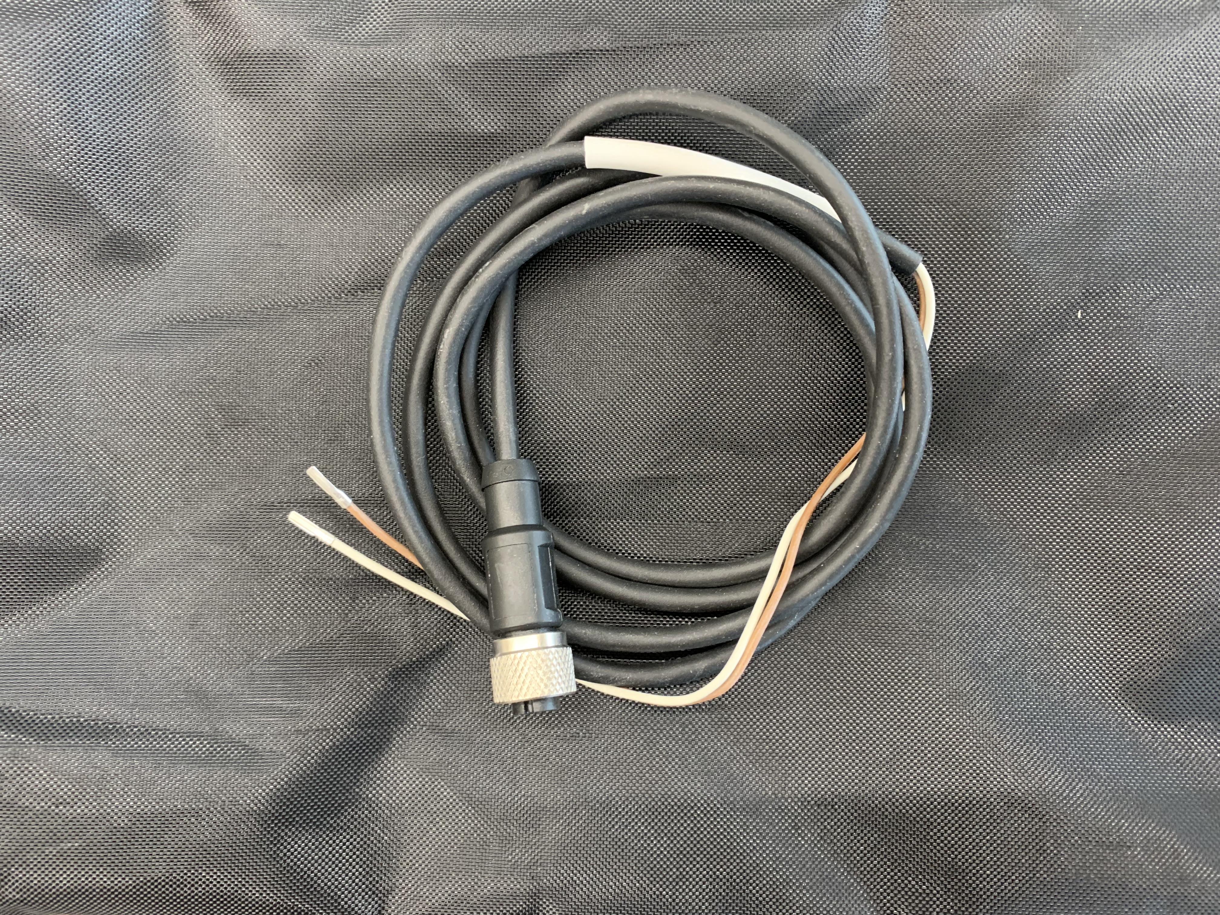
Connect cable cores of high pressure transmitter to terminals 14, 15, 16 of SE-i1
- Screwdriver
- Cable 1 → Terminal 14
- Cable 3 → Terminal 15
- Cable 2→ Terminal 16
- After mounting, check electrical cable connections for tightness!
Connect cable cores of low pressure transmitter to terminals 17, 18, 19 of SE-i1
- Screwdriver
- Cable 1 → Terminal 17
- Cable 3 → Terminal 18
- Cable 2 → Terminal 19
- After mounting, check electrical cable connections for tightness!
Guide connecting cable of "Motor PTC" and "Phase monitoring" into external terminal box
Connect cable cores of PTC resistors for monitoring the motor winding temperature to terminals 8 and 9
- Screwdriver
- After mounting, check electrical cable connections for tightness!
Slide shrinking tubes onto the 3 cable cores of the connecting cable for "Phase monitoring"

Attach cable lugs of Phase monitoring and position shrinking tubes
- Cable 1 → black
- Cable 2 → brown
- Cable 3 → blue
- After mounting, check electrical cable connections for tightness!
Shrink shrinking tubes
Place cables carefully in external terminal box
Configure all BEST SOFTWARE settings and then:
Attach cover of external terminal box
- Phillips screwdriver