Oil flow and oil pressure monitoring
In the case of more complex compressor protection devices, such as the SE-i1 or the previous models SE-C1 and SE-C2, an oil pressure switch or oil flow switch can be connected directly to a signal input of the device and evaluated. The protection function takes into account time delays during start and monitoring to avoid unnecessary shut-offs.
Oil flow monitoring with SE-B*
To enable this function on compressor protection devices without a connection for oil flow monitoring, one or two SE-B* devices can additionally be used as an evaluation unit, combined with a capacitor (C1) used as a timer (see figures below). The polarity of the connection cables on the protective device must be determined with a measuring device.
However, this circuit only works with the SE-B1, -B2 or -B3 compressor protection devices, since these devices do not detect cable short-circuits. Other devices with cable short-circuit detection would interpret a closed contact in case of sufficient flow as a short-circuit and this would immediately trigger the lock-out function.
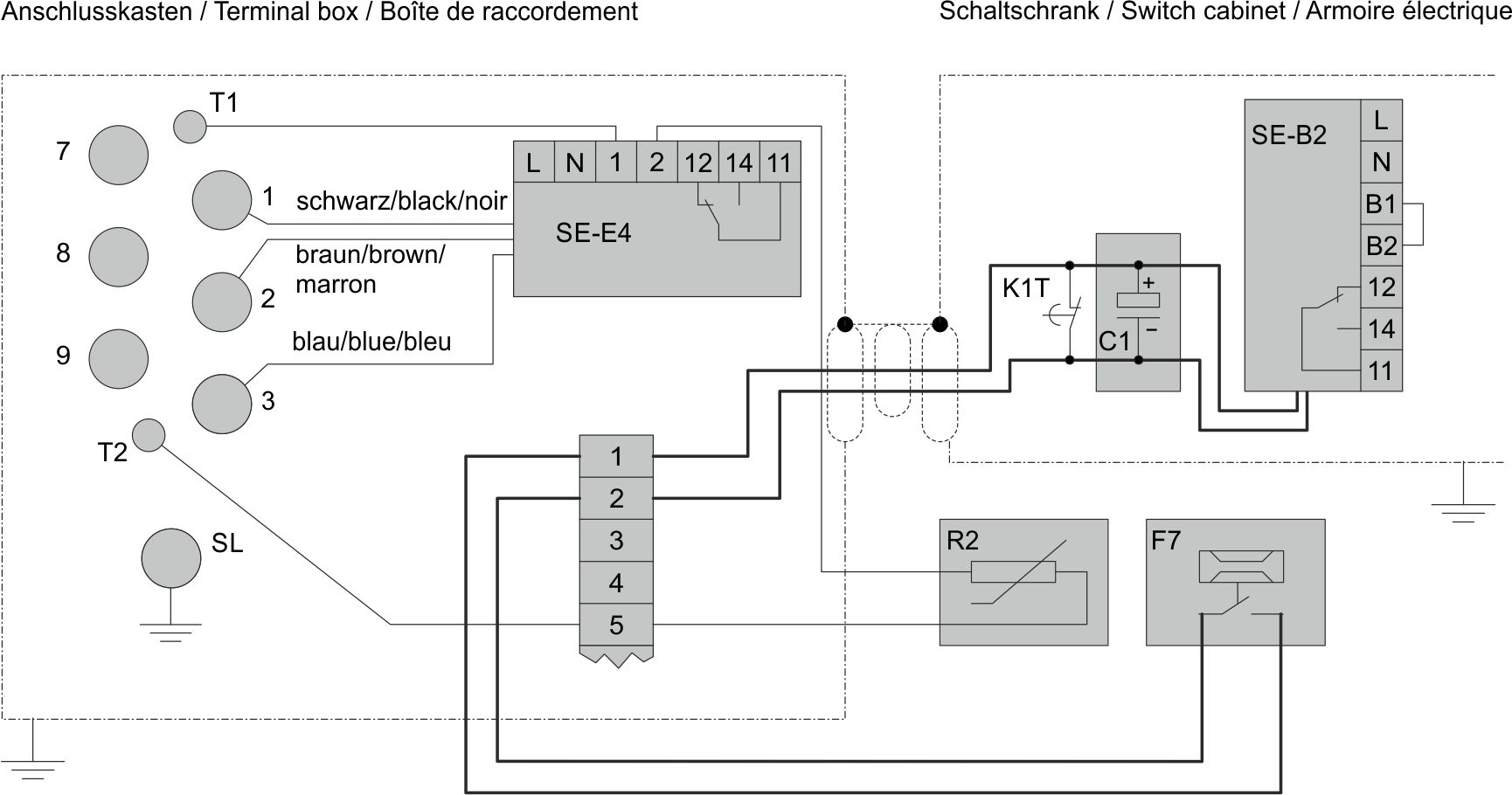
Legend for schematic wiring diagram | ||
|---|---|---|
C1 | Electrolytic capacitor | |
F7 | Oil flow switch | |
F10 | Oil filter monitoring | |
K1T | Time relay "Oil supply monitoring" 20 s after compressor start | |
R2 | Discharge gas and oil temperature sensor | |
| Permanently wired | |
| Wired on site | |


The polarity of the orange connection cables on the SE-B* protective device must be determined with a measuring device.
Legend for schematic wiring diagram | ||
|---|---|---|
C1 | Electrolytic capacitor | |
F7 | Oil flow switch | |
F10 | Oil filter monitoring | |
K1T | Time relay "Oil supply monitoring" 20 s after compressor start | |
R2 | Discharge gas and oil temperature sensor | |
| Permanently wired | |
| Wired on site | |