Application with Bitzer compressors
Motors for part winding start (part winding motors, PW motors) are standard e.g. in:
- Reciprocating compressors 4VES .. 6FE, 4VSL .. 4NSL, 4TME .. 6PME, 4JTE .. 6CTE
Standard: winding partition 50% / 50%, winding type Y/YY, contactors are designed for approx. 60% of the max. operating current. - Reciprocating compressors 8GE .. 8FE
Standard: winding partition 60% / 40%, winding type Δ/ΔΔ, the 1. contactor (PW1) is designed for approx. 70% and the 2. contactor (PW2) for approx. 50% of the max. operating current. - Screw compressors CS.65 .. 85 and HS.53 .. 85
Winding partition 50% / 50%, winding type Δ/ΔΔ, contactors are designed for approx. 60% of the max. operating current.
The time delay until the 2. winding is switched on must be set correctly. For details see the respective operating instructions, e.g.
- KB-100: Operating instructions Semi-hermetic reciprocating compressors
- SB-110: Operating instructions Semi-hermetic screw compressors HS.53 .. 95
- SB-170: Operating instructions Semi-hermetic compact screw compressors CS.65 .. 105
Suitable Bitzer motors for part winding start
For part winding start those motors are suitable in principle which are marked in the Technical Information KT-410 or ST-410 with motor code "..P" and motor connection "Δ/ΔΔ" or "Y/YY":
Voltage range | Nominal voltage | Motor code | Motor connection | Nominal voltage | Voltage range |
|---|---|---|---|---|---|
50 Hz | 60 Hz | ||||
180-200 | 200 | 20P | Y/YY | 200 | 200-230 (220) |
380-415 | 400 | 40P | ∆/∆∆ | 460 | 440-480 |
For a given compressor, an adhesive label in the terminal box cover additionally shows the possible starting modes. For part winding start, the bridges for direct-on-line start may have to be removed.
Starting current for the design of part winding start
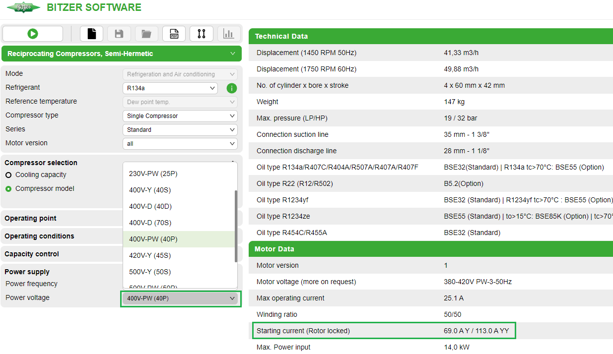
The starting current shown in the Bitzer Software refers to the measured starting current when the rotor of the three phase motor is blocked (mean value of the currents in L1, L2 and L3, measured simultaneously after 4 s). This starting current (locked rotor) refers to the RMS value (root mean square value): To calculate it, the peak value of the corresponding alternating variable (here current) is divided by √2. Operation with 1 winding (Y/Δ) has to be distinguished from operation with 2 windings (YY/ΔΔ). If the compressor starts with the 1. part winding (Y/Δ), switching on the 2. part winding (YY/ΔΔ) does not lead to a significant current peak.
With correct part winding start (start unloading, pressure equalisation), the maximum starting current to be expected is therefore determined by the starting current of the 1. part winding (Y/Δ).
Information in the Bitzer Software
If a specific compressor is selected in the Bitzer Software, the available motors are displayed under "Power supply" - "Power voltage" according to the specified supply frequency (additional motors for North America (UL) under "60Hz UL"). The standard motor is preselected.
The selection corresponds to the specifications in the Technical Information on motor codes:
All further information concerning the motor can be found in the tab "Technical Data" under "Motor data":
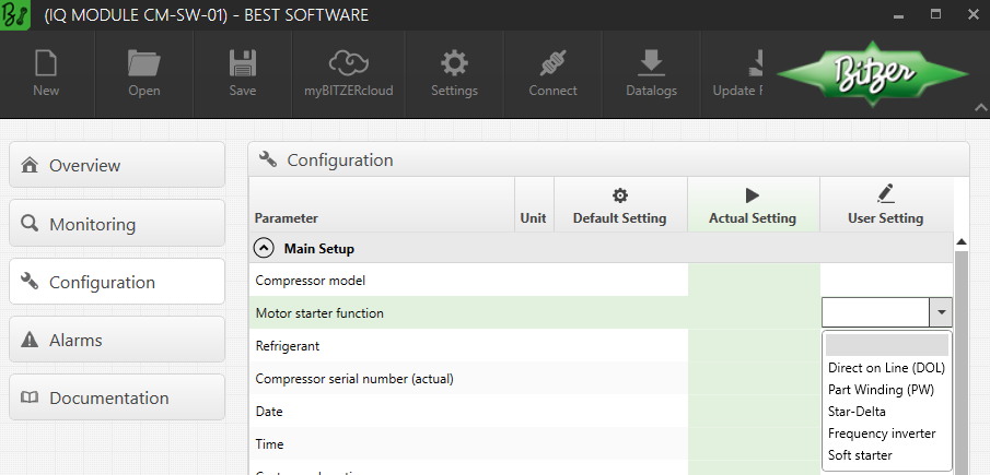
Setting in the Best Software
When using the compressor modules CM-RC or CM-SW, the module controls the contactors for the desired starting mode and, if necessary, the start unloading. For details:
- KT-230: Technical information Compressor module CM-RC-01 for reciprocating compressors
- KT-231: Technical Information Compressor module CM-RC-01 for 8FTE-100K .. 8CTE-140K and 8FTE-100Z .. 8CTE-140Z
- KT-240: Technical Information Compressor module CM-RC-02 for reciprocating compressors
- ST-150: Compressor module CM-SW-01 for screw compressors
The starting mode can be set in the Best Software:
Arrangement of the wiring in the terminal box of the compressor
 WARNING
Risk of electric shock!
Before performing any work in the terminal box: Switch off the main switch and secure it against being switched on again!
Close the terminal box before switching on again!
Observe correct connections!
Wrong arrangement of the electrical connections leads to opposite fields of rotation or rotating fields shifted in phase angle and thus to blocking of the motor!
In the terminal box cover of the Bitzer compressors, an adhesive label shows the possible starting modes and the respective connection of the mains phases to the motor pins. For a direct-on-line start, the cable bridges supplied may have to be mounted.
Arrangement of the wiring for reciprocating compressors:
- KB-100: Operating Instructions Semi-hermetic reciprocating single stage compressors
Arrangement of the wiring for screw compressors:
The following figure shows the internal wiring in the motor:
Q02: contactor for 1. part winding (PW1) resp. compressor contactor (direct-on-line start)
Q03: contactor for 2. part winding (PW2)
(1): bridges for direct-on-line start (optional accessories)
Schematic wiring diagram
In the schematic wiring diagram a part winding start is depicted like this, for example:

Q02: contactor for 1. part winding
Q03: contactor for 2. part winding
M01: motor
Schematic wiring diagrams for Bitzer compressors:
- AT-300: Schematic wiring diagrams for BITZER products