CS. and CSVH series: LI pipe layout
Risk of oil migration and damage to components caused by liquid pressure peaks!
Route the lines for liquid injection (LI) from the connection first upwards!
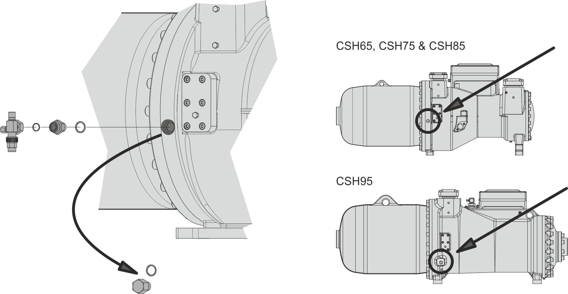
CS.65 .. CS.95, HS.95, OS.95
In these compressors, a separate connection is available for liquid injection (LI). The LI connection leads directly to the pressure-side profile area, after passing through the LI channel. During retrofitting, remove the sealing screw and mount the LI shut-off valve kit (CS., HS.85). The LI channel is designed as a fixed nozzle whose construction is adapted in such a way that the injected amount is adjusted to demand.
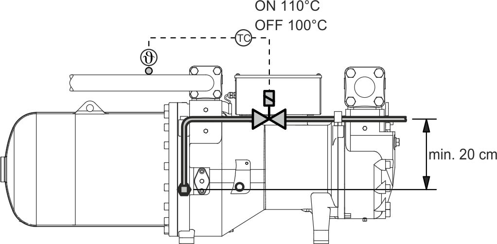
System layout: ECO operation with liquid injection using a compressor from the CSH series as an example
CSVH
As an option, CSVH compressors can be delivered with LI connection. In this case, the LI solenoid valve is wired and controlled by means of the FI. The pipeline comes mounted with a deviation from the compressor to the FI cooling. See following figure, dark-grey pipeline.

dark grey: optional LI connection on CSVH.