Pressure collector
The feed lines to the collector should be designed in the same way as recommended for single compressors (Oil separators HS. and OS.):
- Oil separator below the compressor level or
- oil level in the oil separator below the injection point on the compressor
The discharge gas line must have a sufficient gradient up to the pressure collector to ensure free drainage. Install the pipe sections at the inlet to the pressure collector, preferably tilted approx. 45° to the flow direction (see following figure) or at right angles.
Legend | |
|---|---|
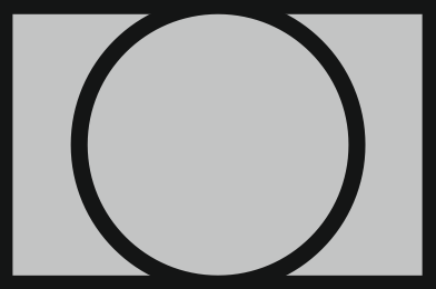
| Sight glass |
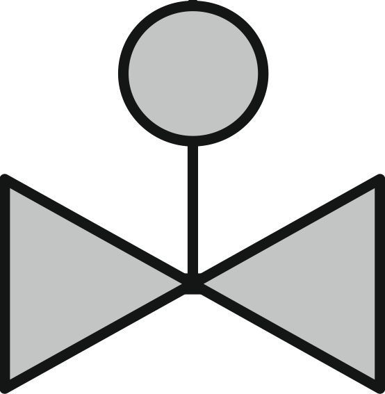
| Control valve |
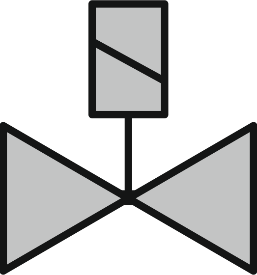
| Solenoid valve |
| Check valve |
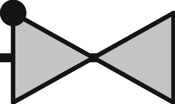
| Shut-off valve |
FZ | Flow limiter |

In order to be able to easily replace compressors later, mounting additional shut-off valves is recommended.
Design the pressure collector as a cross connection with an outlet on one side and feed it into the oil separator as shown. If the pressurised gas inlet to the oil separator is above the level of the pressure collector, pipe as described above (Oil level in the oil separator below the injection point on the compressor).
Oil collection line
Mount the oil collector line over the entire length with a constant diameter. The pipe runs to the individual compressors should be of the same type and as short as possible.
- Instead of individual oil filters, a collective filter of corresponding size can also be used (dashed illustration).
- For easy maintenance, shut-off valves in the pipe runs to the compressors are recommended (low pressure drop – preferably ball valves).