Bitzer water cooled oil coolers
Bitzer offers the following external water cooled oil coolers (not suitable for R717 - NH3):
OWD series
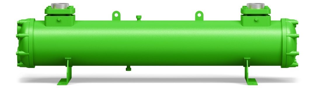
OWD series | Oil volume in refrigerant circuit | Heat transfer fluid volume |
|---|---|---|
allowable fluids | oil according to ISO6743-3, DIN51503-1 | water/brine OWD..B series additionally seawater |
PS max | 32 bar | 10 bar |
PS min | -1 bar | 0 bar |
TS max | 150°C | 95°C |
TS min | -20°C | 4°C |
OW series
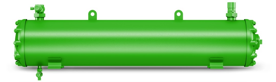
OW Series | Oil volume in refrigerant circuit | Heat transfer fluid volume |
|---|---|---|
allowable fluids | Oil according to ISO6743-3, DIN51503-1 | water/brine OW..B series additionally seawater |
PS max | 28 bar | 10 bar |
PS min | -1 bar | 0 bar |
TS max | 120°C | 95°C |
TS min | -10°C | 4°C |
The values for allowable pressure (PS) and allowable temperature (TS) apply to approval in accordance to the EU Pressure Equipment Directive.
Depending on approval scheme the application ranges may lie within the specified values. For areas of validity outside the European Union, either the sign of the approval organisation or an alternative name plate is affixed to the pressure equipment.
Technical data
OWD series | Weight [kg] | Oil volume [dm3] | Heat transfer fluid volume [dm3] |
|---|---|---|---|
OWD1307(B)-10-.. | 36 | 7.0 | 2.7 |
OWD1307(B)-20-.. | 38 | 6.3 | 3.2 |
OWD1310(B)-20-.. | 46 | 8.4 | 4.1 |
OWD1607(B)-20-.. | 60 | 8.5 | 5.6 |
OWD1610(B)-20-.. | 71 | 11.4 | 7.1 |
OWD1612(B)-20-.. | 77 | 14.5 | 8.5 |
OWD1615(B)-20-.. | 89 | 18.2 | 10.4 |
OWD1618(B)-20-.. | 102 | 22.0 | 12.2 |
OWD2112(B)-20-.. | 125 | 23.6 | 16.3 |
OWD2115(B)-20-.. | 143 | 29.7 | 19.8 |
OWD2118(B)-20-.. | 185 | 35.8 | 23.3 |
OWD2712(B)-20-.. | 198 | 34.5 | 28.3 |
OWD2715(B)-20-.. | 229 | 43.4 | 34.1 |
OWD2718(B)-20-.. | 260 | 52.3 | 39.8 |
OWD3212(B)-20-.. | 263 | 48.2 | 40.4 |
OWD3215(B)-20-.. | 307 | 60.7 | 48.7 |
OWD3218(B)-20-.. | 349 | 73.1 | 57.1 |
OW series | Weight [kg] | Oil volume [dm3] | Heat transfer fluid volume [dm3] |
|---|---|---|---|
OW401(B) | 33 | 10.5 | 2.2 |
OW501(B) | 38 | 14.0 | 2.6 |
OW781(B) | 60 | 18.0 | 4.5 |
OW941(B) | 75 | 24.0 | 5.4 |
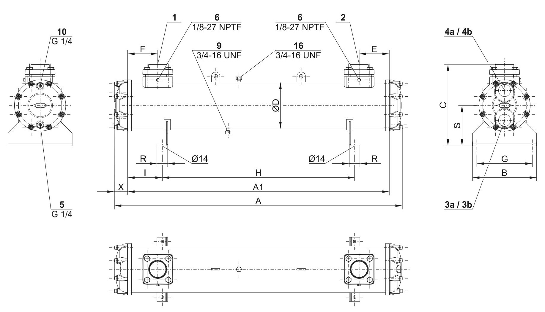
Pipe connections
OWD series
Model | 1 | 2 | 3a | 3b | 4a | 4b | 6 |
|---|---|---|---|---|---|---|---|
OWD1307(B)-10-.. | DN40 | DN40 | G 1 | G 1 | G 1 | G 1 | - |
OWD1307(B)-20-.. | DN40 | DN40 | G 1 | G 1 | G 1 | G 1 | - |
OWD1310(B)-20-.. | DN40 | DN40 | G 1 | G 1 | G 1 | G 1 | - |
OWD1607(B)-20-.. | DN50 | DN50 | G 1 1/2 | G 2 | G 1 1/2 | G 2 | - |
OWD1610(B)-20-.. | DN50 | DN50 | G 1 1/2 | G 2 | G 1 1/2 | G 2 | - |
OWD1612(B)-20-.. | DN50 | DN50 | G 1 1/2 | G 2 | G 1 1/2 | G 2 | - |
OWD1615(B)-20-.. | DN50 | DN50 | G 1 1/2 | G 2 | G 1 1/2 | G 2 | - |
OWD1618(B)-20-.. | DN50 | DN50 | G 1 1/2 | G 2 | G 1 1/2 | G 2 | - |
OWD2112(B)-20-. | DN80 | DN80 | G 2 | G 2 | G 2 | G 2 | ✓ |
OWD2115(B)-20-.. | DN80 | DN80 | G 2 | G 2 | G 2 | G 2 | ✓ |
OWD2118(B)-20-.. | DN80 | DN80 | G 2 | G 2 | G 2 | G 2 | ✓ |
OWD2712(B)-20-.. | DN100 | DN100 | G 2 1/2 | G 4 | G 2 1/2 | G 4 | ✓ |
OWD2715(B)-20-.. | DN100 | DN100 | G 2 1/2 | G 4 | G 2 1/2 | G 4 | ✓ |
OWD2718(B)-20-.. | DN100 | DN100 | G 2 1/2 | G 4 | G 2 1/2 | G 4 | ✓ |
OWD3212(B)-20-.. | DN100 | DN100 | G 4 | G 3 | G 4 | G 3 | ✓ |
OWD3215(B)-20-.. | DN100 | DN100 | G 4 | G 3 | G 4 | G 3 | ✓ |
OWD3218(B)-20-.. | DN100 | DN100 | G 4 | G 3 | G 4 | G 3 | ✓ |
Nominal diameters (DN) are not actual dimensions!
The nominal diameters DN10 .. DN200 only indicate ranges! The number is not a quantifiable unit, it is only indirectly related to the diameters of the connections and should not be used in calculations.
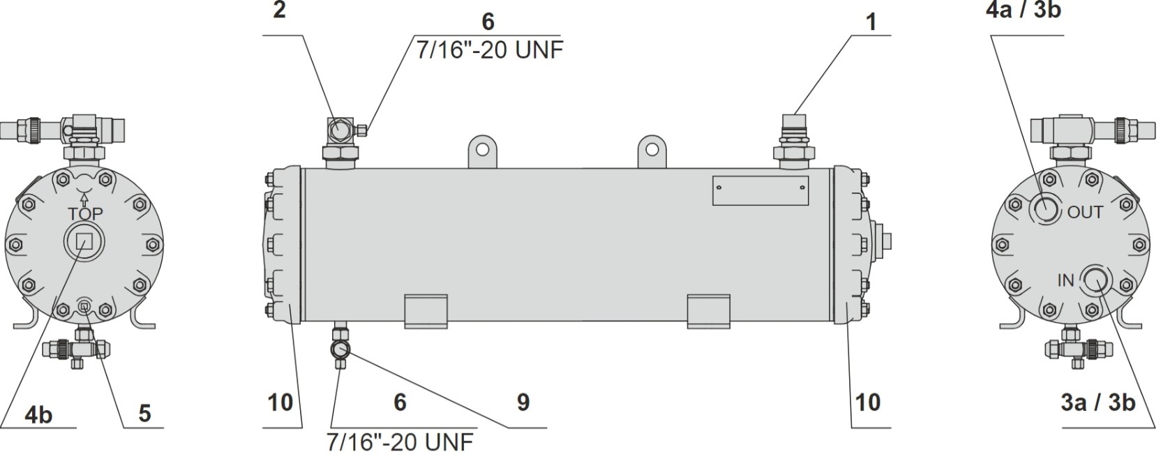
OW series
Model | 1 | 2 | 3a | 3b | 4a | 4b | 5 | 9 |
|---|---|---|---|---|---|---|---|---|
OW401(B) | 22 (7/8'') | 22 (7/8'') | G 3/4 | 2 x G 3/4 | G 3/4 | G 1 | - | 10 |
OW501(B) | 22 (7/8'') | 22 (7/8'') | G 3/4 | 2 X G 3/4 | G 3/4 | G 1 | - | 10 |
OW781(B) | 28 (1 1/8'') | 28 (1 1/8'') | G 1 | 2 x G 1 | G 1 | G 1 1/2 | G 1/4 | 10 |
OW941(B) | 35 (1 3/8'') | 35 (1 3/8'') | G 1 | 2 x G 1 | G 1 | G 1 1/2 | G 1/4 | 10 |
Connection positions | ||
|---|---|---|
1 | Refrigerant or oil inlet | |
2 | Refrigerant or oil outlet | |
2a | Alternative refrigerant outlet | |
3 | Heat transfer fluid inlet | |
3a | 4 or 6 pass | |
3b | 2 or 3 pass | |
4 | Heat transfer fluid outlet | |
4a | 4 or 6 pass | |
4b | 2 or 3 pass | |
5 | Heat transfer fluid drain | |
6 | Connection for pressure gauge | |
7 | Connection for pressure relief valve | |
8 | Sight glass | |
9 | Oil drain | |
10 | Vent plug for heat transfer fluid | |
11 | Lower fixing rails | |
12 | Upper fixing rails | |
13 | Heater connection | |
14 | Measurement connection at heat transfer fluid inlet | |
15 | Measurement connection at heat transfer fluid outlet | |
16 | Vent plug for refrigerant or oil | |
Dimensions, if specified, may have tolerances according to EN ISO 13920-B.
The legend applies to all water cooled shell and tube condensers, discharge gas desuperheaters, oil coolers and all shell and tube evaporators. It includes connection positions that do not exist in every series.
For performance data, dimensional drawings and further information see BITZER SOFTWARE and the respective Operating instructions: