Pipe layout and further system components
 DANGER
Risk of bursting of components and pipes due to liquid overpressure.
Serious injuries are possible.
Make sure not to exceed maximum admissible pressures!
Danger of compressor failure due to flooding with oil at standstill!
Place the solenoid valve in the oil injection line directly next to the compressor (exceptions are OS.85 and HS.85, they have an internal oil stop valve).
For CS. compressors: Position the solenoid valve directly before the oil inlet connection of the compressor and control it electrically in parallel with the compressor contactor (i.e. the solenoid valve is closed when the compressor is stopped).
For all oil connections which are installed subsequently:
Risk of refrigerant loss!
Prior to commissioning the system, check newly mounted pipes for pressure strength and tightness!
- Place the oil cooler in the immediate vicinity of the compressor.
- Design the pipe layout in such a way that no gas cushions can form and a rearward emptying of the oil reservoir into the oil separator during standstill is excluded (place the oil cooler preferably below the compressor / oil separator).
- To simplify maintenance of the oil cooler, it is recommended to install shut-off valves (ball valves) in the oil lines.
- A sight glass for oil flow monitoring is recommended.
- For CSH compressors with a remotely placed oil cooler or if the cleanliness of the components is not ensured, an oil filter is required additionally.
- Oil coolers must be controlled thermostatically (Thermostatic control of the oil cooler).
Oil bypass
For rapid heating of the oil circuit and reduction of pressure loss with cold oil, an oil bypass (possibly also heating of the cooler at standstill) is absolutely necessary if:
- the oil volume of cooler and oil lines is > 25 dm3 (e.g. parallel compounds with common oil cooler) or the oil volume of cooler and oil lines is more than the compressor oil charge (for CSH compressors)
- the oil temperature in the cooler can drop below 20°C during longer standstill periods (e.g. if the oil cooler is installed outdoors or if it is integrated in the condenser)
The oil mixing valve should have a modulating control function. It is a temperature-controlled three-way or flow regulating valve and is shown in the system diagrams as: 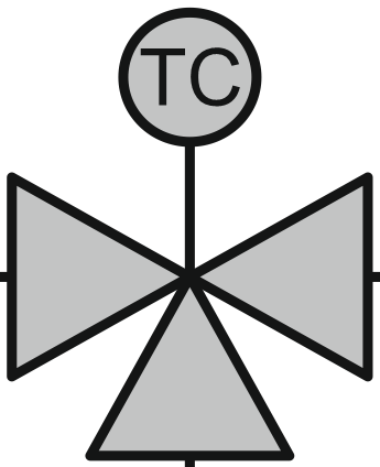 . The use of a solenoid valve (intermittent control) requires maximum response sensitivity of the control thermostat and minimum switching differential (effective temperature fluctuation <10 K).
The oil-side pressure loss in the cooler and pipes should not exceed 0.5 bar in normal operation.
In combination with an automatic pump-down system, increased switching cycles can result. They must be limited to the maximum number of starts per hour by setting the low-pressure limiter and the pause time (time relay) accordingly, as specified in the relevant operating instructions (see list: Introduction). For open drive compressors, observe the specifications of the motor manufacturer. Depending on the operating mode, a single pump-down before switching off may be sufficient.
For HS. and OS. compressors the following is additionally necessary:
- check valve after the oil separator
- pressure equalisation line between oil separator and suction gas line
- Ø 6 mm - 1/4''
- controlled by solenoid valve
- only open at standstill - with parallel compounding, the solenoid valve may only be open when all compressors are switched off
External oil pump
An external oil pump is necessary in systems where no sufficient oil differential pressure can build up directly after the compressor start, e.g:
- in large parallel compound systems with temporarily low condensation temperature, e.g. in winter
- or for boosters with low pressure differences
For such applications, a special version without oil stop valve has been developed for the compressors HSKB85, OSKB85 and OSKAB85. In addition, a solenoid valve is included in the scope of delivery, which must be installed in the oil line.