Compressors for R744 (CO2)
The capacity regulators protrude approximately 9 cm from the surface of the cylinder head. The arrangement can be seen in the following illustrations.
Since the capacity regulators are designed using the bypass principle (Construction and function of the capacity regulators), they can also be used for start unloading.
Maximum equipment of the cylinder banks
Compressors | Equipment of the cylinder banks with capacity regulators |
|---|---|
2-cylinder compressors 2MTE .. 2KTE | max. 1 cylinder head |
4-cylinder compressors 4PTE(M)(U) .. 4KTE(M)(U) | max. 2 cylinder heads |
6-cylinder compressors 6FTE(M)(U) .. 6CTE(M)(U) | max. 2 cylinder heads |
8-cylinder compressors 8FTE .. 8CTE | max. 4 cylinder heads |
Compound systems with a larger number of compressors | for control accuracy etc. see
|
Positions and dimensions with CM-RC-02
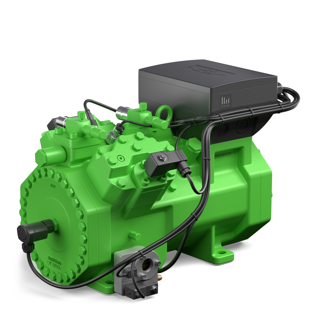
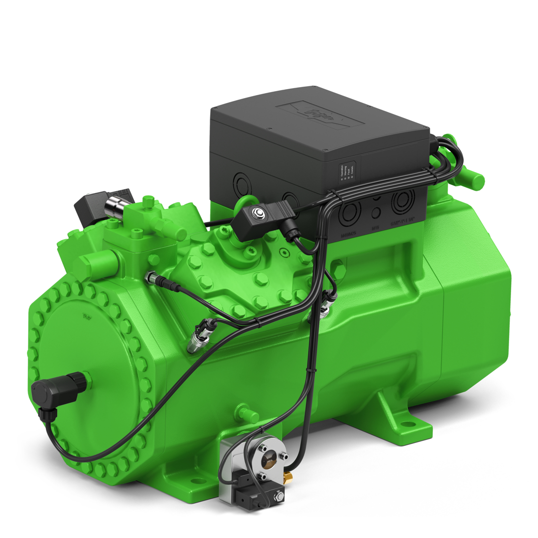
The following illustrations show the positions of the capacity regulators on several compressors for transcritical R744 applications with the compressor module CM-RC-02. The dimensions for other compressors are available in the BITZER Software under the "Dimensions" tab for the respective compressor.
The module housing for the CM-RC-02 has been enlarged compared to the CM-RC-01, meaning that compressors with a CM-RC-02 are approx. 12 mm higher than those with a CM-RC-01.
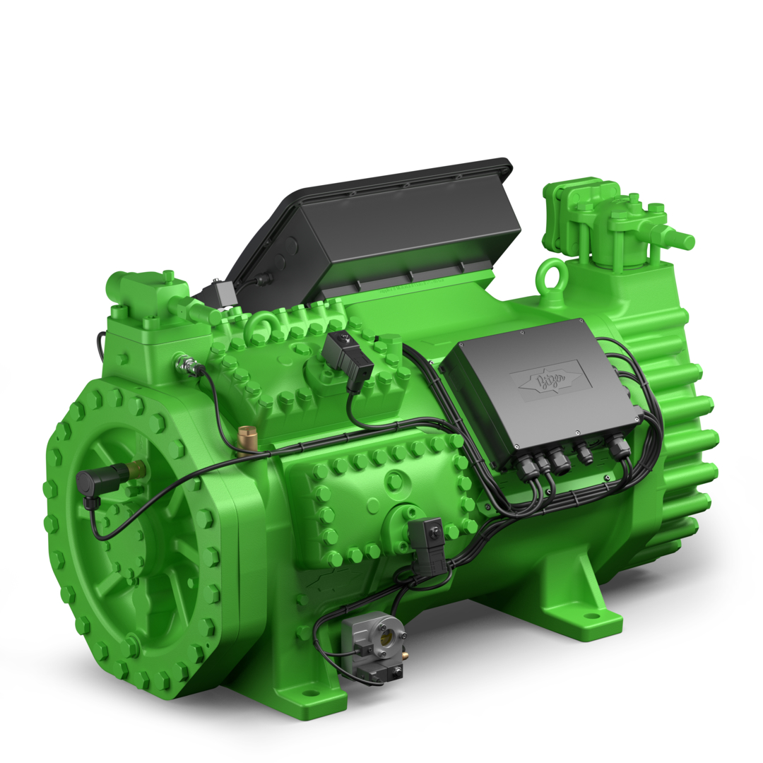
Positions and dimensions with CM-RC-01
The following illustrations show the positions of the capacity regulators in several compressors for transcritical R744 applications with the compressor module CM-RC-01. The module housing for the CM-RC-02 has been enlarged compared to the CM-RC-01, meaning that compressors with a CM-RC-02 are approx. 12 mm higher than those with a CM-RC-01.
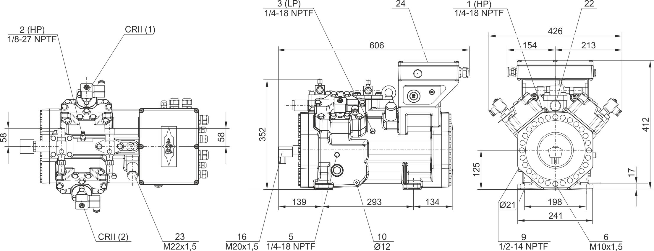
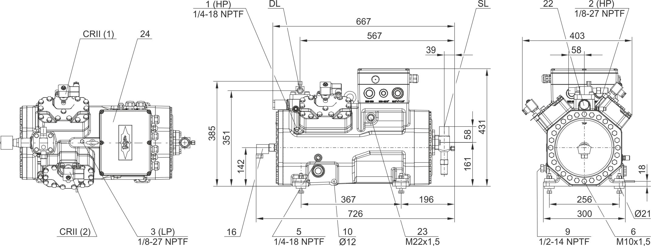
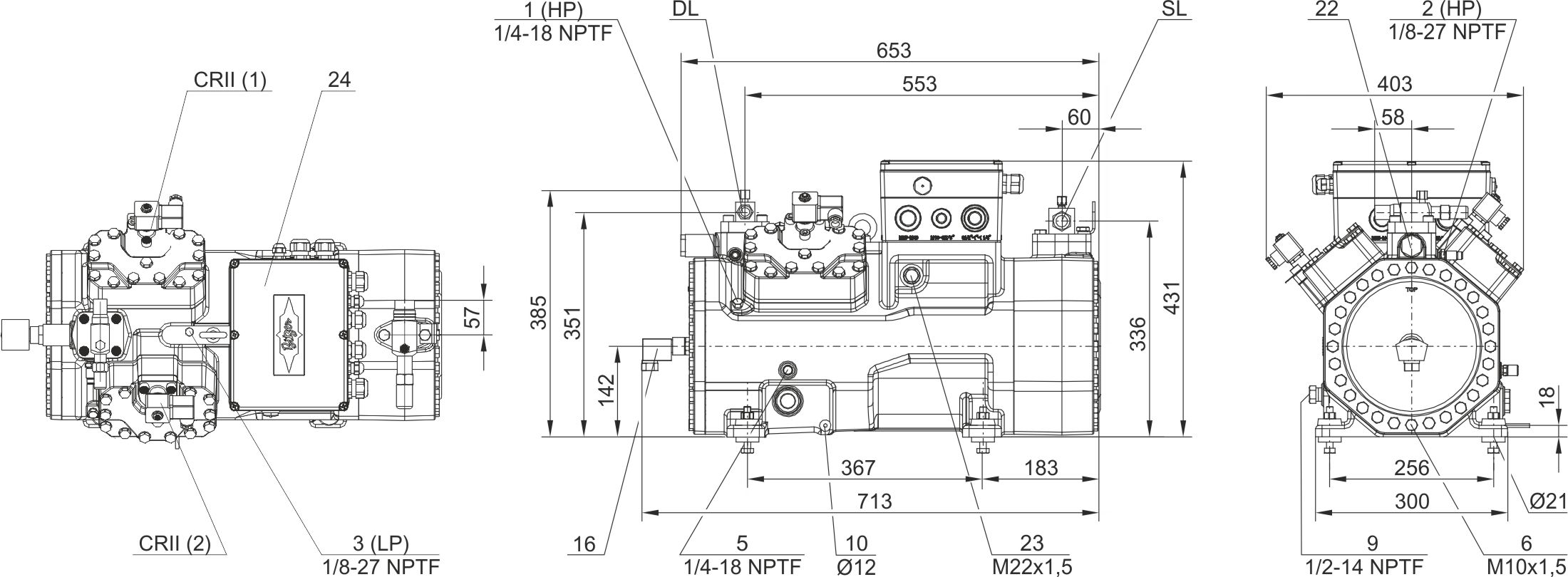
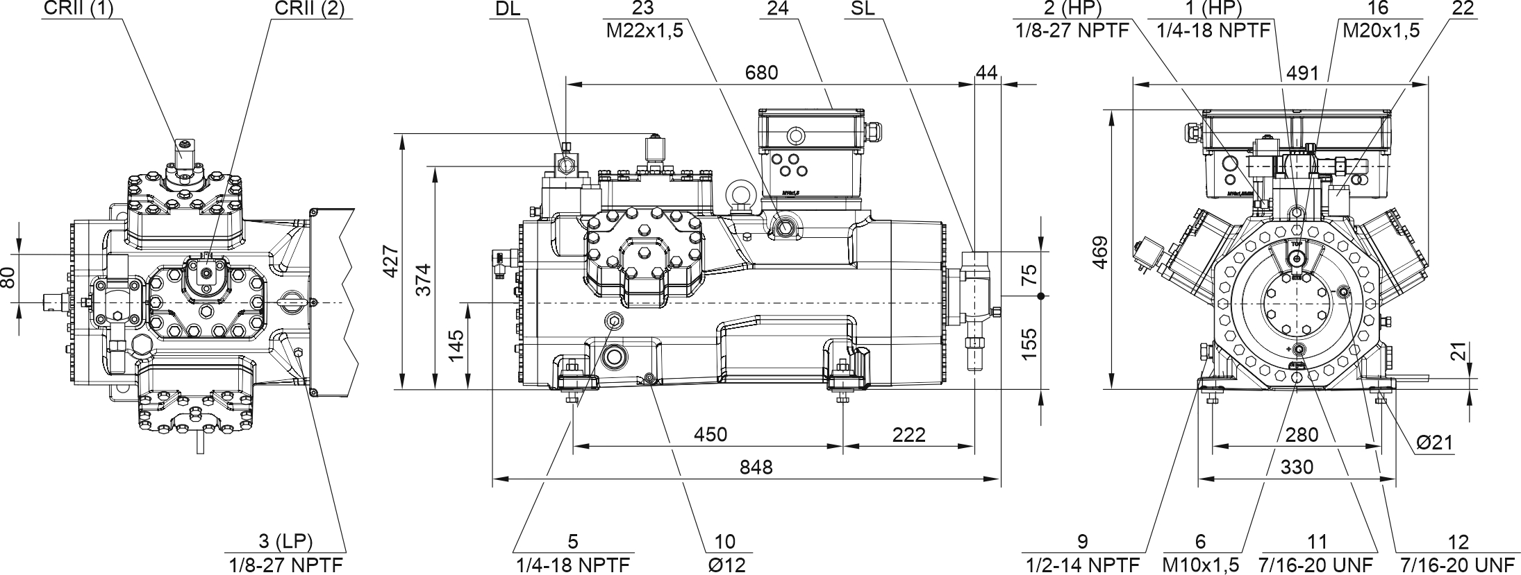
Connection positions | |
|---|---|
1 | High pressure connection (HP) |
1a | Connection for high pressure transmitter (HP) |
2 | Connection for discharge gas temperature sensor (HP) |
3 | Low pressure connection (LP) |
3a | Connection for low pressure transmitter (LP) |
5 | Oil fill plug |
6 | Oil drain |
8 | Oil return (from oil separator) |
9 | Connection for oil and gas equalisation (parallel operation) |
10 | Connection for oil heater |
11 | Oil pressure connection + |
12 | Oil pressure connection – |
16 | Connection for oil monitoring (oil level or oil differential pressure) |
22 | Pressure relief valve to the atmosphere (discharge gas side) |
23 | Pressure relief valve to the atmosphere (suction side) |
24 | Compressor module |
26 | Sight glass |
SL | Suction gas line |
DL | Discharge gas line |
Dimensions may have tolerances according to EN ISO 13920-B.