Compressors for HC, HFC, HFO
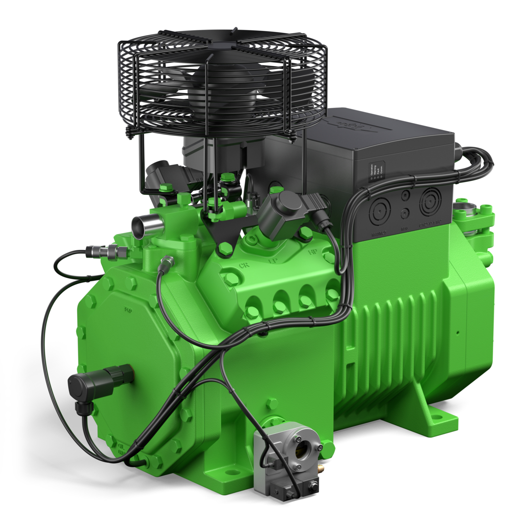
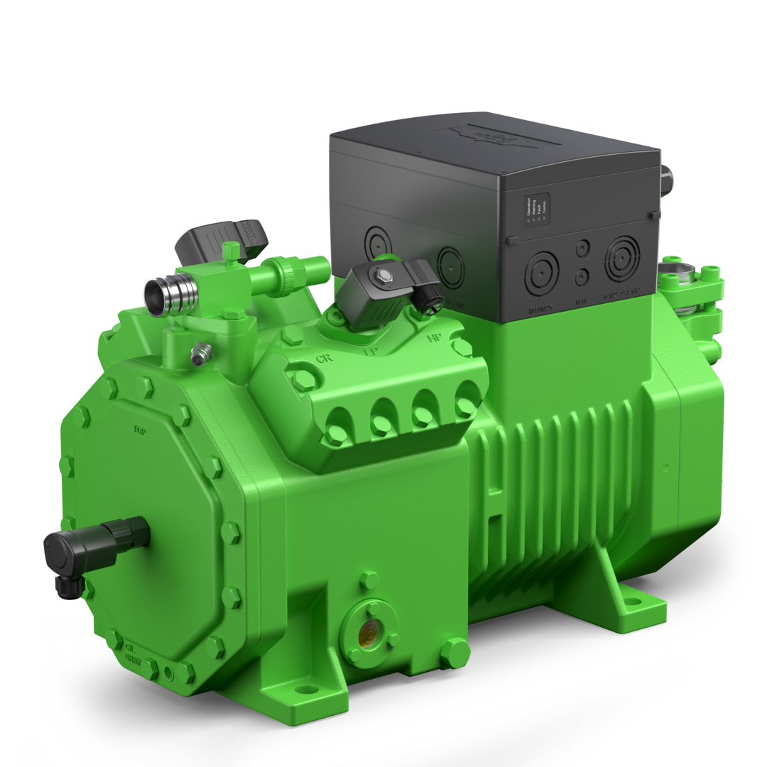
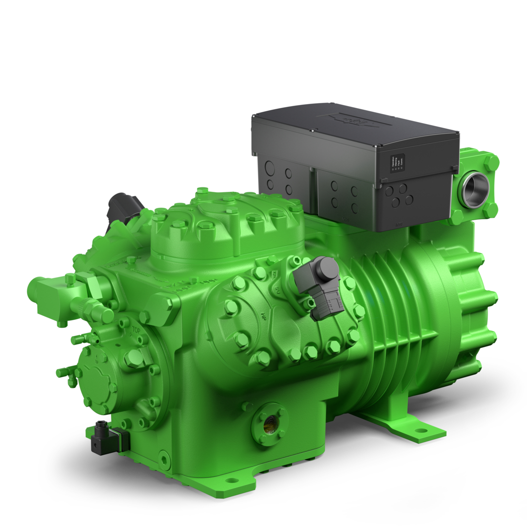
The capacity regulators protrude approximately 9 cm from the surface of the cylinder head. The arrangement can be seen in the following illustrations.
If a cylinder bank is equipped with start unloading, it is no longer available for capacity control. A 4-cylinder compressor can therefore be equipped with either 2 capacity regulators or start unloading and 1 capacity regulator. In 6-cylinder compressors, the third cylinder bank can have an additional capacity regulator.
Maximum equipment of the cylinder banks
Compressors | Equipment of the cylinder banks with capacity regulators |
|---|---|
2-cylinder compressors 2EES(P) .. CES(P) | max. 1 cylinder head |
4-cylinder compressors 4FES(P) .. 4FE(P) | max. 2 cylinder heads |
6-cylinder compressors 6JE(P) .. 6FE(P) | max. 3 cylinder heads |
8-cylinder compressors 8GE(P) .. 8FE(P) | max. 2 cylinder heads |
4-cylinder tandem compressors 44FES .. 44CES | max. 4 cylinder heads |
6-cylinder tandem compressors 66JE .. 66FE | max. 6 cylinder heads |
Compound systems with a larger number of compressors | for control accuracy etc. see
|
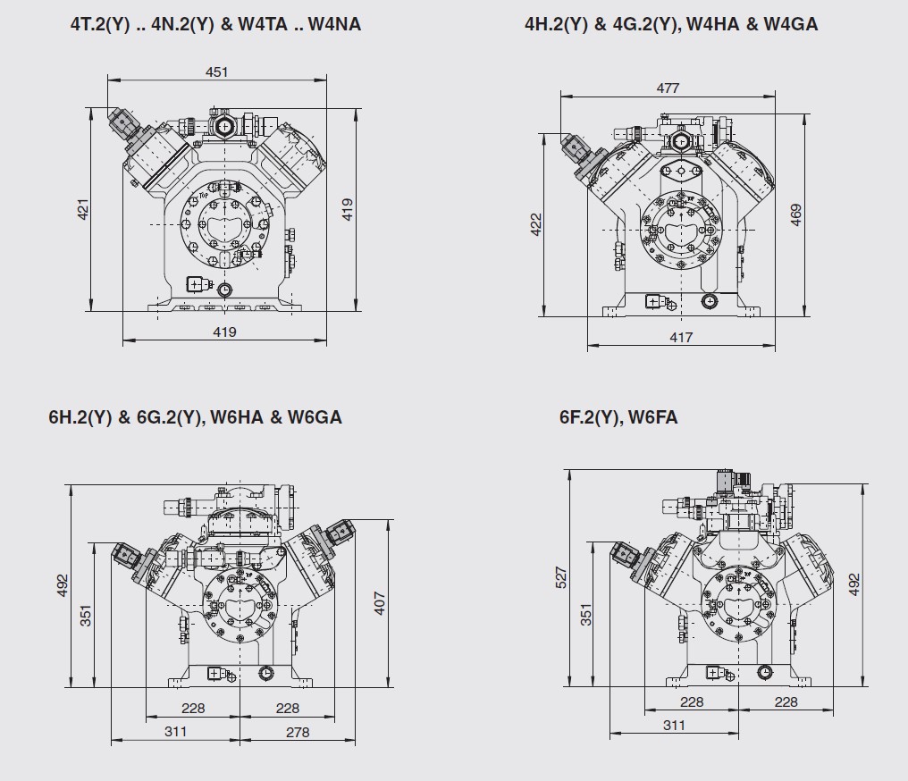
Positions and dimensions
The following illustration shows the positions of the capacity regulators on compressors 2EES(P) .. 8FE(P) (analogous: 2EESH .. 6FEH) without compressor module (CM-RC-01 or CM-RC-02). The exact dimensions with module (but without capacity regulators) are available in the BITZER Software under the "Dimensions" tab for the respective compressor.
Special models 4Z-5.2 .. 4N-20.2
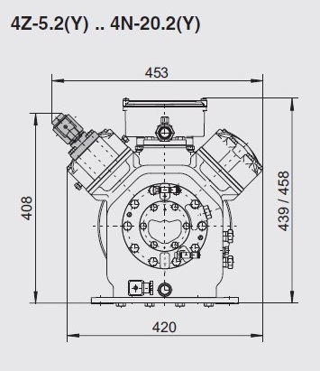
Open drive reciprocating compressors
Compressors | Position |
|---|---|
4Z-5.2 .. 4N-20.2 | cylinder bank opposite the sight glass |
4H.2, 4G.2 | both cylinder banks are possible |
6H.2, 6G.2 | outer cylinder banks |
6F.2 | upper cylinder bank and cylinder bank opposite the sight glass |