Modbus introduction
The VARIPACK has a built-in Modbus RTU interface (XC3) which allows to monitor the frequency inverter. The interface is shared for connecting the fieldbus (Modbus) or the BEST converter. When the fieldbus is connected, the operating parameters can be monitored with the BEST Software by using Ethernet.
Configuration of the Modbus communication parameters
Configuration and default settings can be found in BEST under "Configuration" in the parameter group "Communication".
Setting of the parameters can be done via BEST using the BEST converter or ethernet.
Used data types and scaling
Data types:
- int8: signed 8-bit integer
- uint8: unsigned 8-bit integer
- int16: signed 16-bit integer
- uint16: unsigned 16-bit integer
- uint32: unsigned 32-bit integer
- float32: 32-bit floating point
- string: string
Scaling of the values:
- Scale 1: The value is the exact value
- Scale 10:
- To transmit a value, it must be multiplied by 10, i.e. 12.3 --> 123
- A received value must be divided by 10, i.e. 123 --> 12.3.
- Scale 100:
- To transmit a value, it must be multiplied by 100, i.e. 1.23 --> 123
- A received value must be divided by 100, i.e. 123 --> 1.23
- Scale 1000:
- To transmit a value, it must be multiplied by 1000, i.e. 0.123 --> 123
- A received value must be divided by 1000, i.e. 123 --> 0.123
- Scale 3600:
- A received value must be divided by 3600; i.e. 360000 --> 100
Reading and writing 32-bit values
32-bit values must be read and written as two consecutive Modbus registers (register count = 2).
While Modbus.org has specified that 16-bit values are transmitted with the most significant byte first (or "big endian byte order"), there is no standard for the order of the words that come into play with 32-bit values or character strings with 2 or more registers.
By default, the VARIPACK FDU ... FKU transmits 32-bit values with the least significant word first (or "little endian word order").
However, transmission with the most significant word first (or "big endian word or") can also be activated using parameters.
The following tables show examples of this procedure for the number 123456789, which corresponds to the hexadecimal number 75BCD15.
Least significant word first:
Register X | Register X+1 | |||
|---|---|---|---|---|
Word 0 | Word 1 | |||
Byte 1 | Byte 0 | Byte 3 | Byte 2 | |
Bit 16 .. 9 | Bit 8 .. 0 | Bit 32 .. 25 | Bit 24 .. 17 | |
Binary | 11001101 | 00010101 | 00000111 | 01011011 |
Hexadecimal | CD | 15 | 07 | 5B |
Most significant word first
Register X | Register X+1 | |||
|---|---|---|---|---|
Word 1 | Word 0 | |||
Byte 3 | Byte 2 | Byte 1 | Byte 0 | |
Bit 32 .. 25 | Bit 24 .. 17 | Bit 16 .. 9 | Bit 8 .. 0 | |
Binary | 00000111 | 01011011 | 11001101 | 00010101 |
Hexadecimal | 07 | 5B | CD | 15 |
Reading string values via Modbus
One byte can be used to transmit one character via ASCII code. One word or register therefore allows two characters to be transmitted.
In order to be able to transmit longer character strings, therefore, usually multiple registers are used for the string data type.
The number of registers to be read is listed in "Number of registers".
The character strings are transferred from left to right and always with the most significant word and the least significant byte first (also "big endian word order" and "little endian byte order") .
The following table shows an example of this procedure for the character string ABCD, which is provided in a string with 3 registers.
Register X | Register X+1 | Register X+2 | ||||
|---|---|---|---|---|---|---|
Word 2 | Word 1 | Word 0 | ||||
Byte 4 | Byte 5 | Byte 2 | Byte 3 | Byte 0 | Byte 1 | |
Bit 40 .. 33 | Bit 48 .. 41 | Bit 24 .. 17 | Bit 32 .. 25 | Bit 8 .. 0 | Bit 16 .. 9 | |
Binary | 01000010 | 01000001 | 01000100 | 01000011 | 00000000 | 00000000 |
Hexadecimal | 42 | 41 | 44 | 43 | 0 | 0 |
ASCII | B | A | D | C | ||
Special case:
With VARIPACK of the 1st generation, the first 4 characters of character strings are transmitted twice. To avoid this, the first two registers should be ignored.
For this purpose, the register address should be increased by 2 and the number of registers reduced by 2 compared to the documentation.
Modbus function codes
The following function codes have been implemented from the standard Modbus protocol:
Function | Code (hexadecimal) | Code (decimal) |
|---|---|---|
Read holding registers (H) | 03 | 03 |
Read input register (I) | 04 | 04 |
Write single register (H) | 06 | 06 |
Write multiple registers (H) | 10 | 16 |
Read/write multiple registers (H) | 17 | 23 |
All input registers (I) can also be read as holding registers (H).
Modbus exception codes
The following exception codes have been implemented from the standard Modbus protocol:
Code | Name | Meaning |
|---|---|---|
01 | Illegal function | The function code is not valid. |
02 | Illegal data address | The specified register is not valid. |
03 | Illegal data value | The value is not allowed. |
04 | Server device failure | Unrecoverable error in server device. |
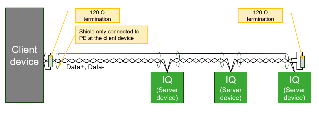
Wiring recommendations
- The cable must be shielded, twisted pair suitable for RS485 communication with a recommended characteristic impedance of 100 .. 130 Ω. The two signal wires must be in the same pair of wires.
- The wiring topology must be daisy chain with 120 Ω termination resistors at each end of the bus line. The VARIPACK is equipped with a small switch located right of the interface bush which allows to switch the respective terminating resistor on or off.
- Switch in right position: Terminating resistor is not set (factory setting).
- Switch in left position: Terminating resistor is connected (set).
- The maximum possible cable length of the Modbus line depends on the used baud rate and the number of devices.
- The Modbus cable should be routed so that the influence from the power cables is minimized. When crossing power cables, a 90° angle should be achieved. Modbus and power cables that run in parallel should be separated by the largest possible appropriate clearance distance, approximately 20 .. 25 cm. A grounded shield plate or grounded metal duct can be used instead.
- The maximum recommended number of IQ products on one Modbus line is 10 devices. If other equipment is connected to the same Modbus line, the maximum current sourcing of the other equipment must be observed. The total bias resistance of the complete string should be at least 450 Ohm. This IQ product has a bias resistance of 10 kOhm (→ 1 kOhm with 10 units).
- The CSV and VARIPACK of the 1st generation have a galvanically isolated RS485 interface.
- The shield must only be connected at one end of the bus (preferable at the client device) in order to avoid unwanted ground current in shielding. Only Data+ and Data- need to be connected. COM1 GND may be connected if required by the client device. However, the shield must be unbroken along the complete bus length.

See wiring example below.