Modbus introduction
The ECOLITE controller has a built-in Modbus RTU interface (11), which is in general dedicated for BEST.
Nevertheless, it is also possible to use this interface for fieldbus purposes. It allows to monitor the condensing unit as well as to perform parameter changes via a superior controller or a building management system. But as the ECOLITE controller can´t detect whether the BEST converter or any other device is connected, the communication with BEST isn´t possible anymore when the Modbus communication parameters have been changed from the default settings.
A cable with MOLEX plug can be ordered with part no. 344 117 10.
Configuration of the Modbus communication parameters
Default settings:
- Modbus address: 1
- Baud rate: 19200
- Parity: even
- Stop bits: 1 (not configurable)
The Modbus communication parameters can be changed via the keypad of the controller:
- Enter the Modbus communication parameters menu (CF)
- Press F1 + F3 --> FREE
- Press F2 + F4 --> Par (in the right lower end "ABC" is shown)
- Press F4 --> CF
- Press F4 --> CF30
- Change the communication settings
(press F1/F3 to move up-/downwards between the parameters, press F4 to enter/leave the parameter) - CF30 = Address: 1 .. 255
- CF31 = Baud rate:
3 = 9600
4 = 19200 - CF32 = Parity
1 = Even
2 = None
3 = Odd - Power cycle the controller to activate the new communication settings
When the communication parameters are changed from default, the communication with the BEST Software is not possible any more!
Used data types and scaling
Data types:
- uint8: unsigned 8-bit integer
- int16: signed 16-bit integer
- uint16: unsigned 16-bit integer
- uint32: unsigned 32-bit integer
Scaling of the values:
- Scale 1: The value is the exact value
- Scale 10:
- To transmit a value, it must be multiplied by 10, i.e. 12.3 --> 123
- A received value must be divided by 10, i.e. 123 --> 12.3
- Scale 1000:
- To transmit a value, it must be multiplied by 1000, i.e. 1.23 --> 1230
- A received value must be divided by 1000, i.e. 1230 --> 1.23
Reading and writing 32-bit values
32-bit values must be read and written as two consecutive Modbus registers (register count = 2).
While Modbus.org has specified that 16-bit values are transmitted with the most significant byte first (or "big endian byte order"), there is no standard for the order of the words that come into play with 32-bit values or character strings with 2 or more registers.
This device transmits 32-bit values with the least significant word first (or "little endian word order").
The following table shows an example of this procedure for the number 123456789, which corresponds to the hexadecimal number 75BCD15.
Register X | Register X+1 | |||
|---|---|---|---|---|
Word 0 | Word 1 | |||
Byte 1 | Byte 0 | Byte 3 | Byte 2 | |
Bit 16 .. 9 | Bit 8 .. 0 | Bit 32 .. 25 | Bit 24 .. 17 | |
Binary | 11001101 | 00010101 | 00000111 | 01011011 |
Hexadecimal | CD | 15 | 07 | 5B |
Modbus function codes
The following function codes have been implemented from the standard Modbus protocol:
Function | Code (hexadecimal) | Code (decimal) |
|---|---|---|
Read holding registers (H) | 03 | 03 |
Read input register (I) | 04 | 04 |
Write single register (H) | 06 | 06 |
Write multiple registers (H) | 10 | 16 |
Read/write multiple registers (H) | 17 | 23 |
All input registers (I) can also be read as holding registers (H).
Defect of the controller!
Continuous writing of parameters may lead to a wear out of the EEPROM as a lot of the parameters will be directly written into the EEPROM, even when they don´t change their value. Cyclic writing of parameters must be avoided.
Modbus exception codes
The following exception codes have been implemented from the standard Modbus protocol:
Code | Name | Meaning |
|---|---|---|
01 | Illegal function | The function code is not valid. |
02 | Illegal data address | The specified register is not valid. |
03 | Illegal data value | The value is not allowed. |
04 | Server device failure | Unrecoverable error in server device. |
Wiring recommendations
- The cable must be shielded, twisted pair suitable for RS485 communication with a recommended characteristic impedance of 100 .. 130 Ω. The two signal wires must be in the same pair of wires.
- The wiring topology must be daisy chain with 120 Ω termination resistors at each end of the bus line. As this IQ product has no integrated termination resistor, it must be added externally.
- The maximum possible cable length of the Modbus line depends on the used baud rate and the number of devices.
- The Modbus cable should be routed so that the influence from the power cables is minimized. When crossing power cables, a 90° angle should be achieved. Modbus and power cables that run in parallel should be separated by the largest possible appropriate clearance distance, approximately 20 .. 25 cm. A grounded shield plate or grounded metal duct can be used instead.
- The maximum recommended number of IQ products on one Modbus line is 10 devices. If other equipment is connected to the same Modbus line, the maximum current sourcing of the other equipment must be observed.
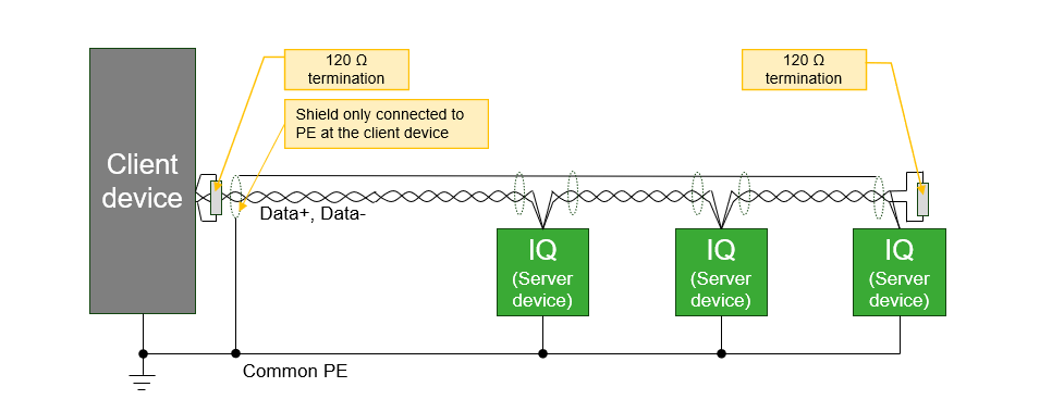
- This IQ product has no galvanic isolation in the RS485 interface. Therefore, modules connected directly by RS485 bus must share the same PE ground potential.
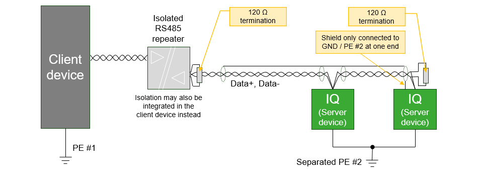
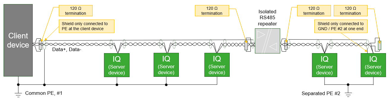
- IQ products that refer to different ground potentials must be connected on RS485 via a suitable galvanic isolated repeater, or only to equipment with an isolated RS485 interface. Different potentials across the bus line can cause the electronics to malfunction or be damaged.
- Only Data+ and Data- should be connected. GND wire should not be connected between modules since this can cause unwanted ground current in the communication wire. However, the GND pin may be used for single-ended connection of shield when no better possibility for connecting the shield is available.
- The shield must only be connected at one end of the bus to avoid unwanted ground current in shielding. However, the shield must be unbroken along the complete bus length, except across galvanic isolated repeaters.
- In case of an isolated client device and non isolated server devices or vice versa, it is recommended to connect the shield at the end without isolation.
- When none of the devices is isolated, the shield should be connected at the client device. When all devices are isolated, it doesn't matter at which end the shield is connected - but it should not be connected to the GND pin of the RS485 interface.
See wiring examples below.