Booster system for medium and low temperature application with flash gas bypass
In 2008, systems with "flash gas bypass (FGB)" also became standard R744 system designs due to their simple design.
- Systems with single stage compression, two-stage expansion and flash gas bypass for a useful temperature level e.g. medium temperature applications.
- This system design provides for a separator in which liquid and gaseous R744 are separated from each other. This takes place at intermediate pressure and will be referred to in the description hereafter as an intermediate pressure vessel.
- The pressure inside the intermediate pressure vessel is controlled by a flash gas bypass valve. The pressure level here is above the required evaporation pressure/above the suction pressure of the medium temperature compressors.
- However, the system is usually set up and used as a booster system for two different useful temperature levels, e.g. medium temperature application and low temperature application.
- It is composed of, among other things:
- Two compressor stages (normal refrigeration and deep-freeze compressor stage)
- with a common refrigerant and oil circuit
- with two-stage expansion for each evaporator temperature level/evaporator pressure level
- an intermediate pressure vessel and
- a flash gas bypass.
- Two-stage compression is achieved by two single stage compressors connected in series.
- The operation of this standard system cools with the help of dry evaporators ("direct expansion").
- The refrigeration compressor stage in a booster system is a subcritical application.
Further features of a booster system with flash gas bypass
- After flowing through the gas cooler/condenser, the refrigerant is relaxed to intermediate pressure with the aid of a high-pressure control valve in the intermediate pressure vessel; gas and liquid phases are separated from each other:
- The resulting flash gas is fed to the compressors of the medium temperature compressor stage via a flash gas bypass valve,
- the liquid is led to the evaporators of the low and medium temperature application.
- This flash gas bypass can be used to lower the intermediate pressure to a defined set point (e.g. 35–40 bar). However, the mass flow from the intermediate pressure vessel to the evaporators is then also reduced. The increased available enthalpy difference during evaporation compensates for this.
- Unlike a simple refrigerating circuit or a cascade system, the temperature of the liquid refrigerant is higher than the saturation temperature on the high pressure side of the low temperature compressors. This means that less evaporation enthalpy is available to the evaporators, which must definitely be taken into account when selecting the compressors by means of a higher mass flow!
- Since the low temperature compressors feed the refrigerant directly into the suction header of the medium temperature compressor stage, the specific compression work is lower than in a cascade system due to the lower pressure ratio.
- The suction gas temperature of a compressor of the medium temperature compressor stage results from the three mass flows – low temperature mass flow, medium temperature mass flow and mass flow of the flash gas – which all have different temperatures.
Important points in system planning and system design
In addition to operational safety and efficiency, the influence of different load conditions during operation is decisive in the planning and design of R744 booster systems.
- The most extreme load conditions ("worst case conditions") must always be calculated and taken into account, i.e.:
- Both the full load conditions at maximum ambient temperatures over several hours (simultaneous operation/simultaneity factor 0.8–0.85), as well as the
- Operating conditions at minimum load at low ambient temperatures and within/outside opening hours ("shop open" and "shop closed").
Based on these calculations, it is possible to answer the following questions:
- Is the capacity control of the compressors optimally set? (Capacity control).
- For example, can a high control accuracy (CF) (Parameters and recommendations for optimal system efficiency and operational safety) be achieved with minimal changes in performance when connecting and disconnecting follow-up compressors?
- Can stable operation be guaranteed without frequent start-up and shut-off of the compressor(s) at minimum load conditions?
- Are the suction gas and discharge gas temperatures within the application limit(s) of the compressor(s)?
In order to optimise the operating conditions and avoid critical operating conditions, additional components such as liquid suction line heat exchangers, discharge gas desuperheaters, an increased number of compressors, or auxiliary systems such as refrigerant injection may have to be considered.
- Critical operating conditions caused by unfavourable load conditions include:
- A low load on the evaporators of the medium temperature compressor stage and a simultaneous high load on the evaporators of the low temperature compressor stage:
- This leads to high suction gas temperatures in the medium temperature compressors and thus influences the engine cooling and discharge gas temperature and
- The reverse case, i.e. a high load on the evaporators of the medium temperature compressor stage and a simultaneous low load on the evaporators of the low temperature compressor stage:
- This leads to low suction gas temperatures with low oil sump temperatures and possible wet operation due to too much liquid content in the flash gas.
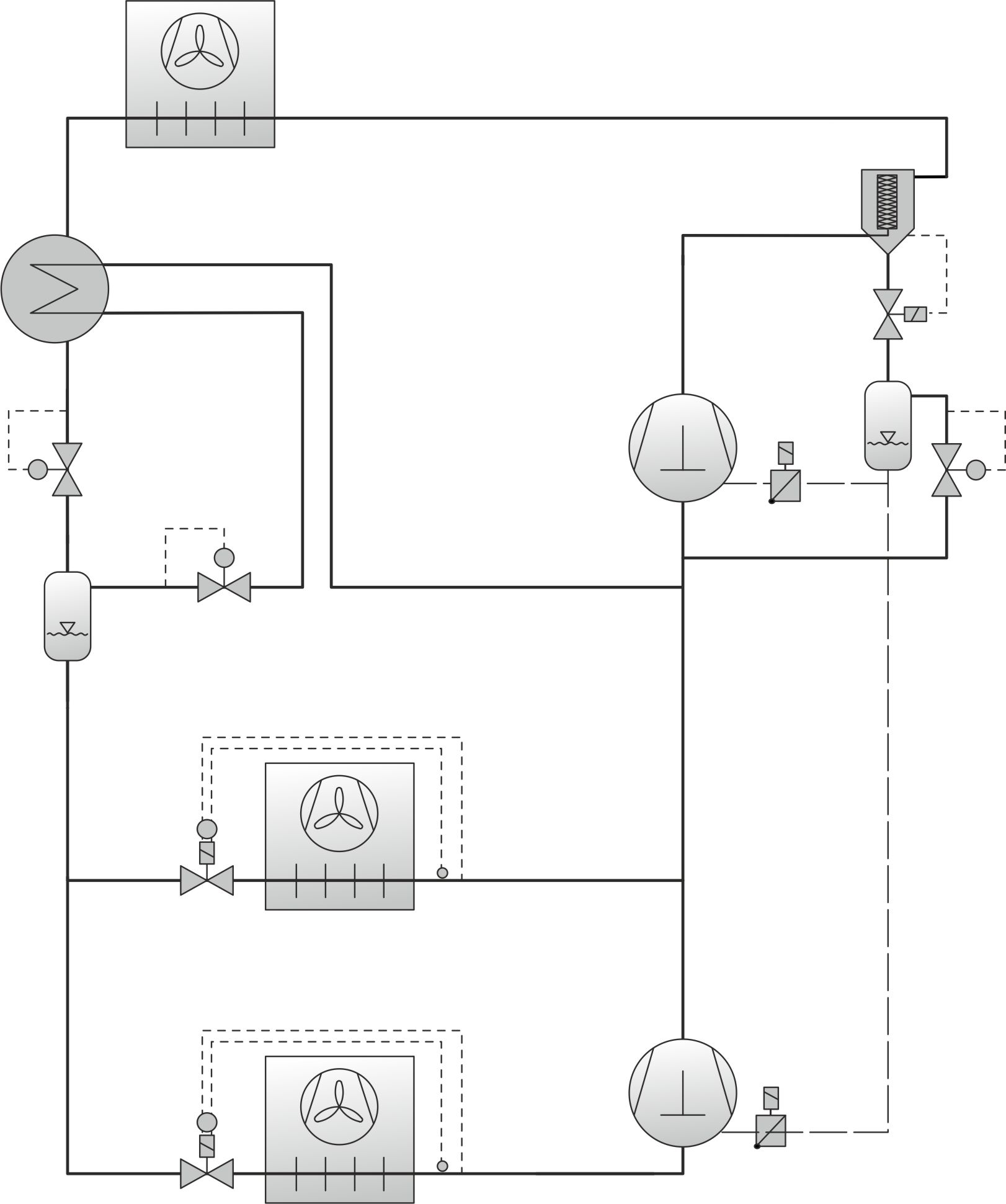
application with flash gas bypass (simplified representation)
flash gas bypass in the p-h-diagram
Low temperature compressor stage:
1-2 | Compression |
2-3 | Desuperheating |
4-11 | Expansion |
11-12 | Evaporation |
12-1 | Overheating suction gas line |
Medium temperature compressor stage:
1-2 | Compression |
2-4 | Gas cooling/condensation |
4-5 | Internal heat exchanger/subcooling |
5-7 | Relaxation to intermediate pressure |
7-8 | Liquid outlet at the intermediate pressure vessel |
8-11 | Relaxation to evaporation pressure |
11-12 | Evaporation |
12-1 | Total overheating |
7-15 | Gas outlet at the intermediate pressure vessel |
15-16 | Expansion to evaporation pressure |