Design example of an ejector in a high lift application
The mass flow ratio as a function of the high pressure and the pressure lift is decisive for the design of an ejector in a high lift application. The pressure stroke itself is a variable that can be freely selected within certain limits and has a major influence on the selection of compressors in the individual compressor stages.
When selecting an ejector, the control strategy must first be determined.
Either:
- the intermediate pressure is varied depending on the high pressure so that parallel compressors and ejectors are operated within the optimum range.
Although this promises the highest efficiency of the system, it also means increased control effort.
Or:
- the intermediate pressure is kept constant. This is easier to implement.
In the following example, an ejector is to be selected for a low temperature/medium temperature booster system with parallel compression:
Boundary conditions:
- Gas cooler outlet temperature (tgc) at the design point: 35°C
- Evaporation temperature in the medium temperature compressor stage (to MT): -8°C
- Evaporation temperature in the low temperature compressor stage (to LT): -28°C
- Cooling capacity of the medium temperature compressor stage (Qo MT): 60 kW
- Cooling capacity of the low temperature compressor stage (Qo LT): 15 kW
- Intermediate pressure, absolute (pIP): 37 bar
First, a system without ejector with a standard superheat is calculated in the BITZER SOFTWARE under R744 booster, see following figure:
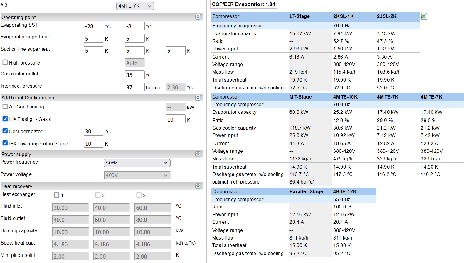
At the gas cooler outlet there is a motive mass flow of 1132 kg/h (MT) + 811 kg/h (parallel) = 1943. The pressure lift that the ejector must carry out from medium temperature level to intermediate pressure level is 9 bar (see figure below).
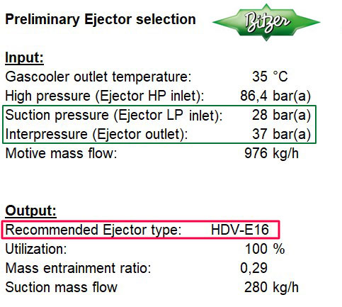
Based on the motive mass flow (mass flow of the medium temperature and parallel compressors) of 1943 kg/h, the high pressure and the pressure stroke, one ejector or several ejectors can be selected.
Two HDV-E16 ejectors are suitable for this design variant to fully utilise the motive mass flow. In this case, both ejectors operate at 100% opening degree. The ejectors should be designed and controlled such that the operating point is as close as possible to 100% opening degree. Individual ejectors can be deactivated in order to make greater use of the still activated ejectors working at part load. This must be done at the latest when their opening degree falls below 30%, as no significant mass flow can be sucked in and compressed below this point. The ejector would then only work as a pure expansion device with isenthalpic throttling.
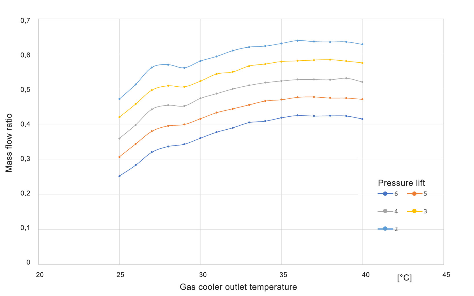
The two ejectors proposed by the BITZER calculation tool have a mass flow ratio of 0.29 at a high pressure of 86.4 bar and at a pressure lift of 9 bar. The total mass flow sucked in and delivered to intermediate pressure is 560 kg/h (2x 280 kg/h).
These results will be included in the further steps of the design. The medium temperature compressors are relieved by 560 kg/h and the parallel compressors are loaded accordingly. Since BITZER SOFTWARE always ideally adapts the parallel compressors to the mass flows of the medium temperature and low temperature compressors, the additional load shift introduced by the ejector must be specified as "high temperature load" (in this case approx. 37 kW). This increases the delivered mass flow of the parallel compressors by 560 kg/h.
The new conditions are:
- Medium temperature compressor: 572 kg/h
- Parallel compressor: 1371 kg/h
- Of which high temperature load for ejector simulation: approx. 37 kW (corresponds to the mass flow of 560 kg/h)
The shift in mass flows has significantly changed the compressor selection (see following figure). The 4MTE-10K compressor, originally used in the medium temperature compressor stage, now appears in the parallel compressor stage.
However, it should be kept in mind that the elimination of the mass flow from the evaporator at the mixing point with the discharge gas of the low temperature compressor stage has greatly increased the mixing temperature and thus the suction gas temperature. This results in a sharp increase of the discharge gas temperature and must be considered in extreme cases. Additional suction gas cooling may be necessary!
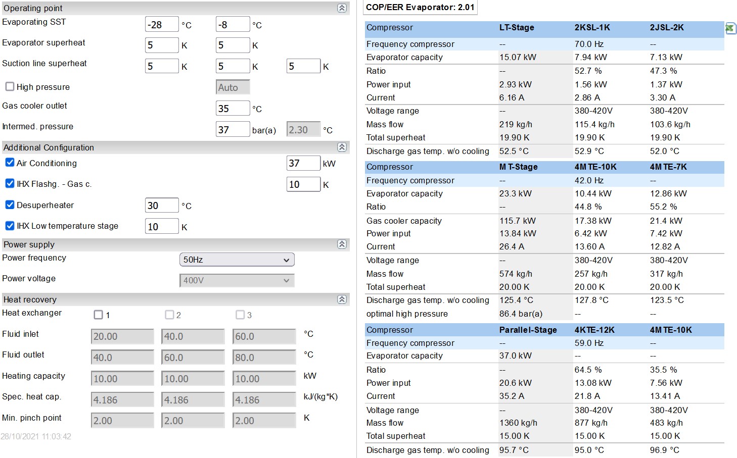
The cooling capacity of the compressor stages shown in the new selection has no meaning. Only the compressor selection was adapted to the new mass flow ratios to determine the compressor sizes and power consumption. Thus, with the originally calculated cooling capacity and the new power consumption due to the use of the ejector, the following COP can be calculated:
COP
The total COP of the parallel system is:
Qo / Pe = (15.07 kW + 60 kW) / (2.93 kW + 25.8 kW + 12.16 kW) = 1.84
The total COP of the parallel + ejector system is:
Qo / Pe = (15.07 kW + 60 kW) / (2.93 kW + 13.84 kW + 20.6 kW) = 2.01