ECOLITE LHL7E
Last revision of the diagram:
15.11.2023
Abbr. | Component |
|---|---|
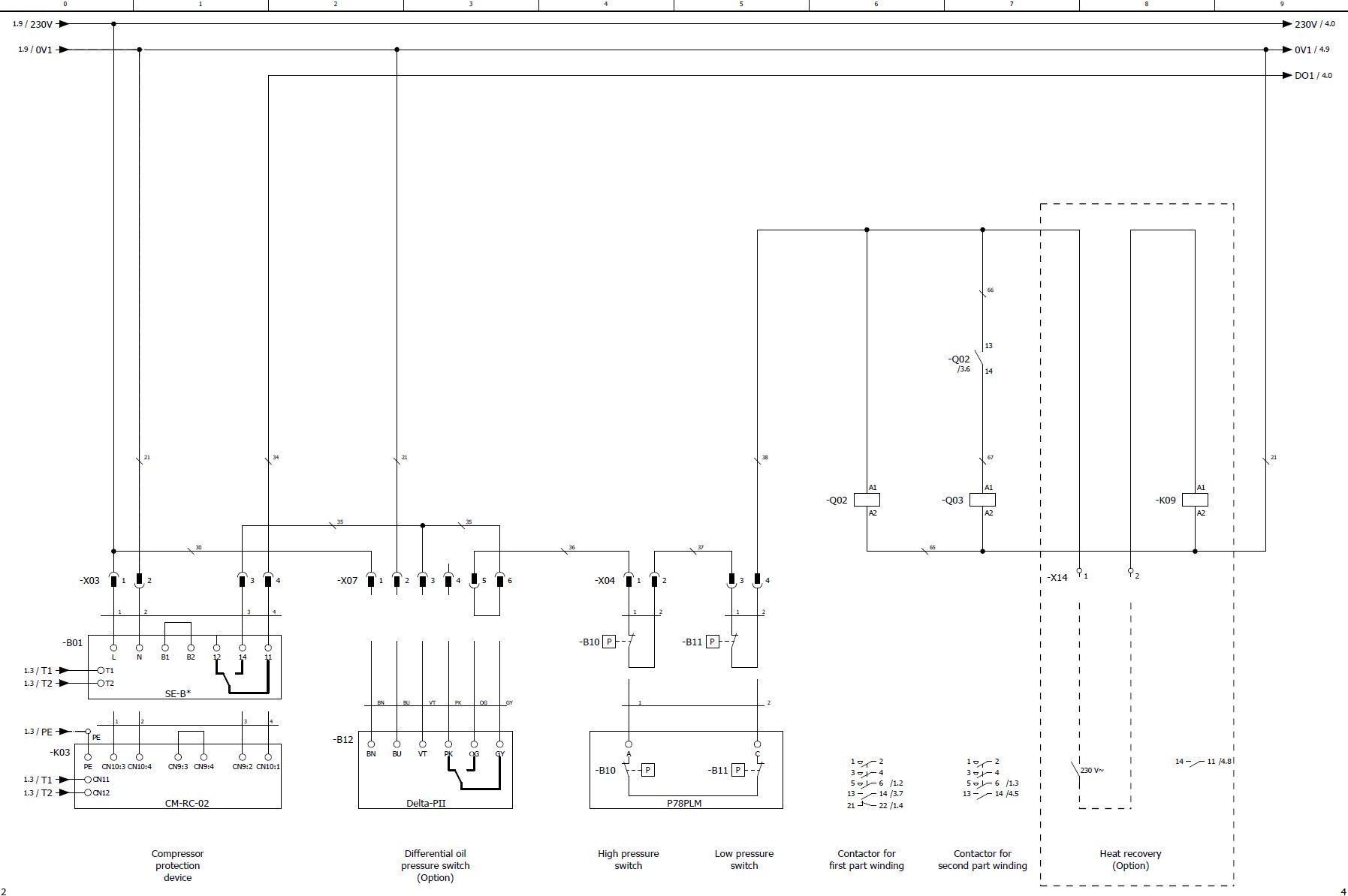
B01 | Compressor protection device |
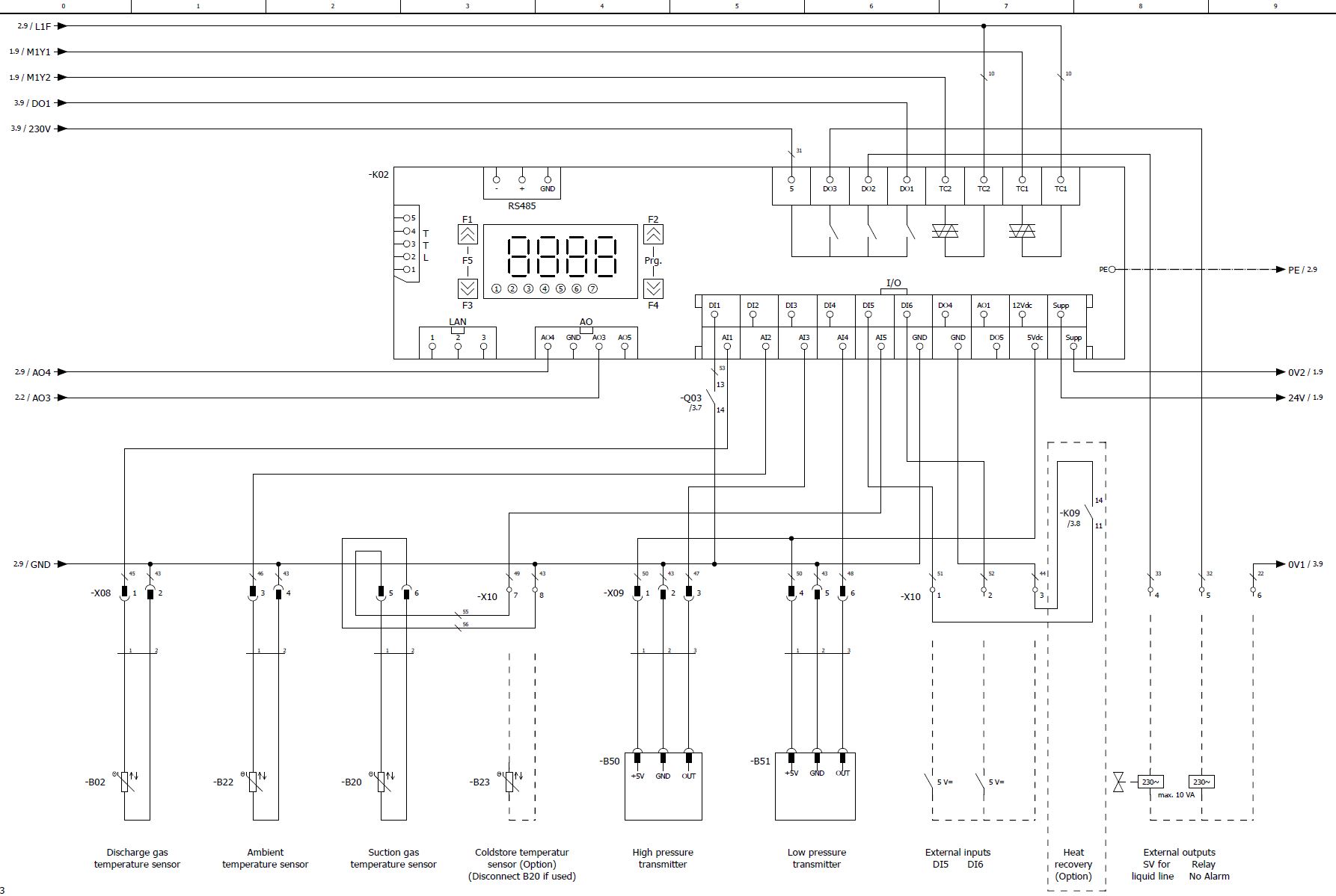
B02 | Discharge gas temperature sensor |
B10 | High pressure switch |
B11 | Low pressure switch |
B12 | Differential oil pressure switch |
B20 | Suction gas temperature sensor |
B22 | Ambient temperature sensor |
B23 | Cold store temperature sensor |
B50 | High pressure transmitter |
B51 | Low pressure transmitter |
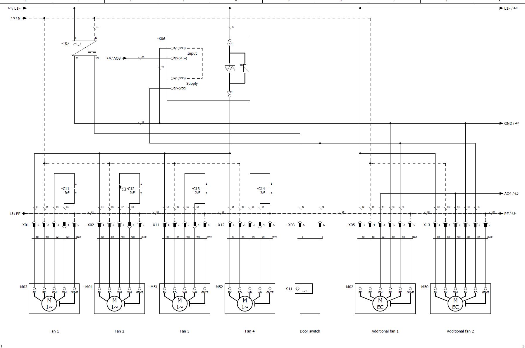
C11 | Run capacitor for fan 1 |
C12 | Run capacitor for fan 2 |
C13 | Run capacitor for fan 3 |
C14 | Run capacitor for fan 4 |
E01 | Oil heater |
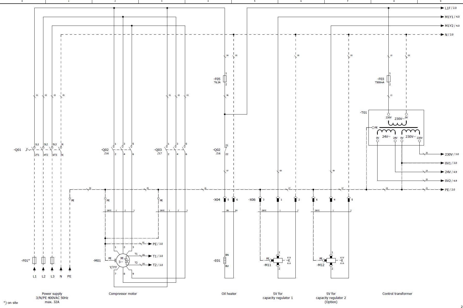
F01 | Main fuse |
F03 | Control circuit fuse |
F05 | Fuse of oil heater |
K02 | Controller of condensing unit |
K03 | Compressor module |
K06 | Fan(s) control module |
K09 | Auxiliary relay for heat recovery |
M01 | Compressor motor |
M02 | Additional fan |
M03 | Fan 1 |
M04 | Fan 2 |
M11 | SV for capacity regulator 1, CR1, CR+, CRII-2 or start unloading |
M12 | SV for capacity regulator 2, CR2, CR- or CRII-1 |
M50 | Additional fan 2 |
M51 | Fan 3 |
M52 | Fan 4 |
Q01 | Main switch |
Q02 | Contactor for first part winding (PW) or main contactor (Y/Δ) or compressor contactor (DOL) |
Q03 | Contactor for second part winding (PW) or delta contactor (Y/Δ) |
S11 | Door switch |
T01 | Control transformer (example for 230 V, required according to EN60204-1) |
T07 | Power supply device for auxiliary voltage |
The cable colours are noted in accordance with IEC DIN60757.
Technical documents for further information:
- KB-206: Operating instructions Ecolite - Air-cooled condensing units