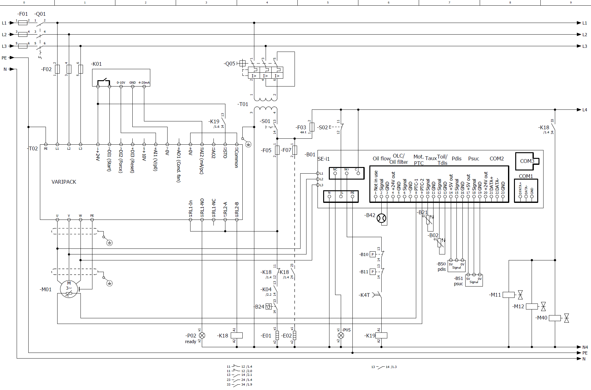
HS.53 .. 74 with VARIPACK and SE-i1
Last revision of the diagram:
13.07.2021
Abbr. | Component |
|---|---|
B01 | Compressor protection device |
B02 | Discharge gas temperature sensor |
B10 | High pressure switch |
B11 | Low pressure switch |
B12 | Differential oil pressure switch |
B21 | Optional temperature sensor |
B24 | Oil thermostat |
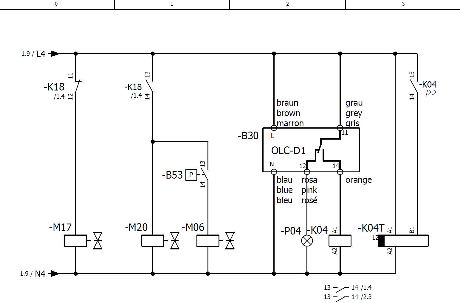
B30 | Oil level switch |
B41 | Oil filter monitoring |
B42 | Oil flow switch |
B50 | High pressure transmitter |
B51 | Low pressure transmitter |
B53 | ECO switch-on |
E01 | Oil heater |
E02 | Terminal box cover heater |
F01 | Main fuse |
F02 | Compressor fuse |
F03 | Control circuit fuse |
F05 | Fuse of oil heater |
F07 | Fuse of terminal box cover heater |
K01 | Superior controller |
K04 | Auxiliary relay for oil monitoring |
K04T | Time relay for oil level switch |
K14 | Auxiliary relay |
K18 | Auxiliary relay: FI outputs power voltage/rotating field for motor |
K19 | Auxiliary relay: safety chain enabled |
K23 | Extension module |
M01 | Compressor motor |
M03 | Fan 1 |
M06 | SV for economiser (ECO) |
M11 | SV for capacity regulator 1, CR1, CR+, CRII-2 or start unloading |
M12 | SV for capacity regulator 2, CR2, CR- or CRII-1 |
M13 | SV for capacity regulator 3, CR3 or CRII-3 |
M14 | SV for capacity regulator CR4 |
M17 | SV for standstill bypass |
M20 | SV for liquid line |
M40 | SV for oil injection |
P02 | Light: compressor is ready-to-operate |
P04 | Light: oil supply fault |
P05 | Light: compressor fault |
Q01 | Main switch |
Q05 | Control transformer fuse |
S01 | Control switch (on-off) |
S02 | Reset of compressor safety chain |
S04 | Reset of oil monitoring |
S13 | Condensing temperature: Switching to second setpoint |
S14 | Evaporation temperature: Switching to second setpoint |
T01 | Control transformer (example for 230 V, required according to EN60204-1) |
T02 | Frequency inverter (FI) |
Technical documents for further information: