ECOLITE LHL3E and LHL5E
Last revision of the diagram:
15.11.2023
Abbr. | Component | |
|---|---|---|
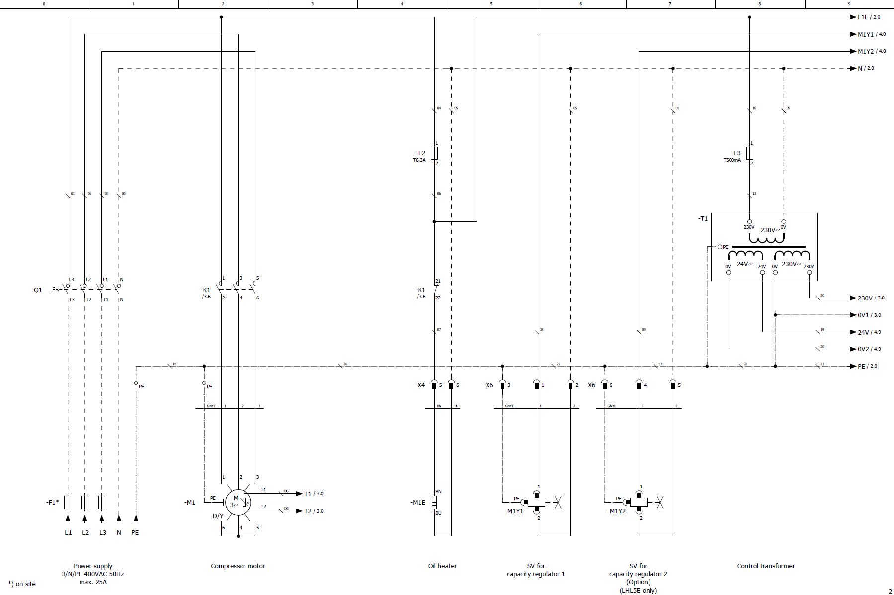
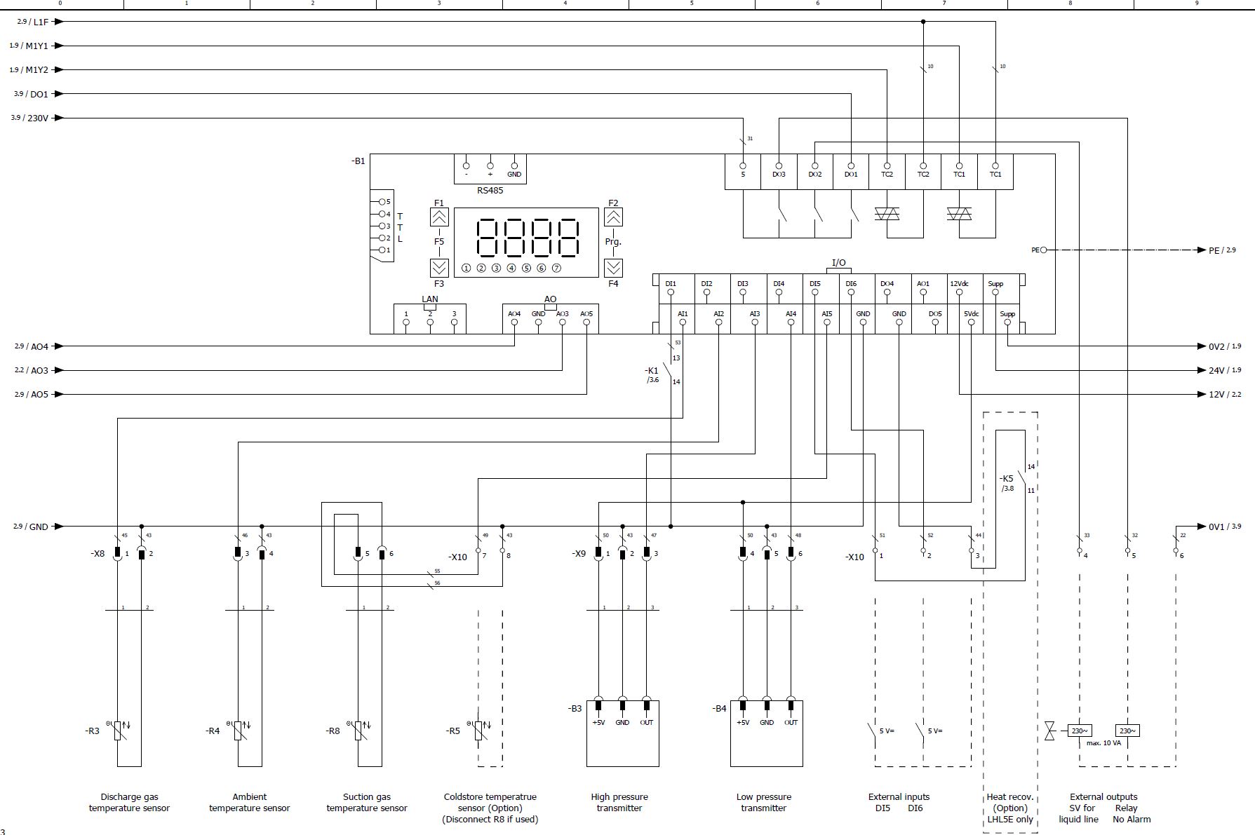
B1 | Controller | |
B3 | High pressure transmitter (liquid line) | |
B4 | Low pressure transmitter (suction gas line) | |
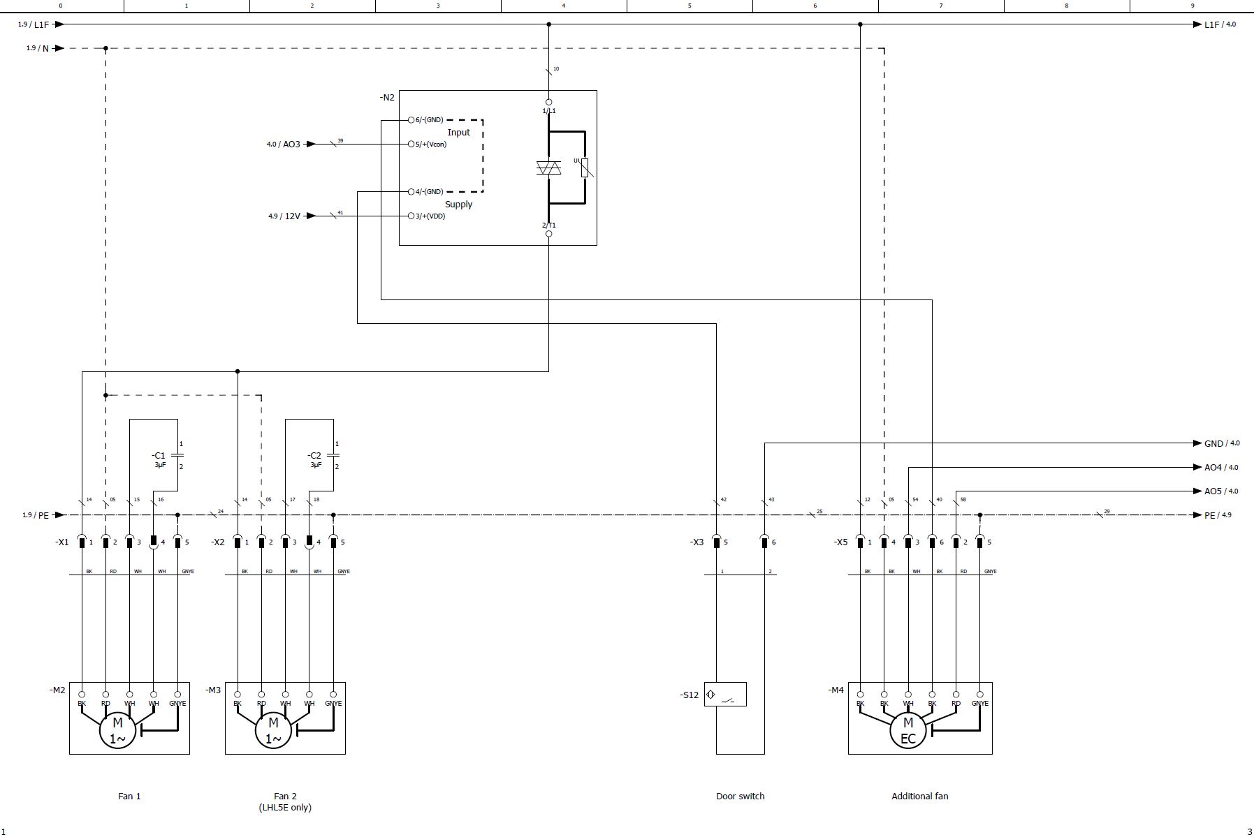
C1 | Operating capacitor fan 1 | |
C2 | Operating capacitor fan 2 | |
F2 | Fuse rating 230 V | |
F3 | Control circuit fuse | |
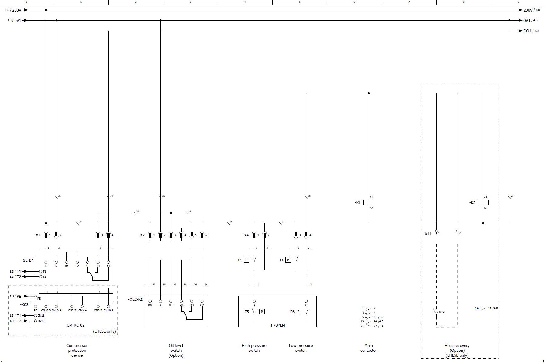
F5 | High pressure switch | |
F6 | Low pressure switch | |
K1 | Main contactor | |
K03 | Compressor module | |
K5 | Relais heat recovery (option, only LHL5E) | |
M1 | Compressor | |
M1E | Oil heater | |
M1Y1 | CRII SV1 | |
M1Y2 | CRII SV2 (option, only LHL5E) | |
M2 | Fan 1 | |
M3 | Fan 2 (only LHL5E) | |
M4 | Additional fan | |
N2 | Fan control module | |
OLC-K1 | Oil monitoring (option) | |
Q1 | Service switch | |
R3 | Discharge gas temperature sensor | |
R4 | Ambient temperature sensor | |
R5 | Cold store temperature sensor (option) | |
R8 | Suction gas temperature sensor | |
SE-B* | Protection device | |
S12 | Door switch | |
T1 | Control transformer |
The cable colours are noted in accordance with IEC DIN60757.
Technical documents for further information:
- KB-206: Operating instructions Ecolite - Air-cooled condensing units