CSV. without STO
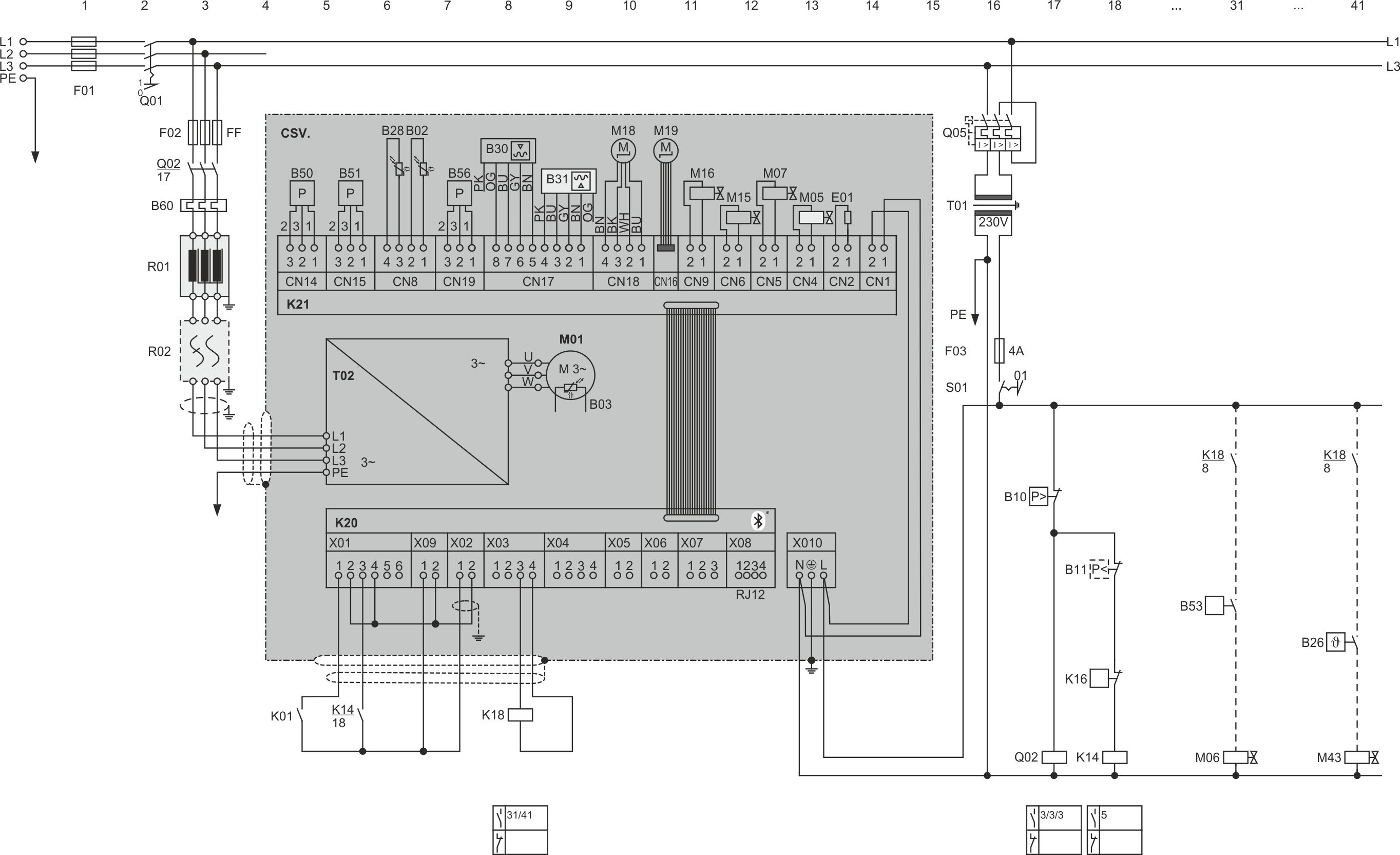
The two components shown in light grey on the extension board (K21) are retrofittable options: The oil level switch for the maximum oil level (B31) can be retrofitted to all compressor models, whilst the LI solenoid valve (M07) can only be retrofitted to CSVH models.
Last revision of the diagram:
12.05.2026
Abbr. | Component |
|---|---|
B02 | Discharge gas temperature sensor |
B03 | Motor temperature sensor |
B10 | High pressure switch |
B11 | Low pressure switch |
B26 | Control thermostat for additonal oil injection, CSV.: for oil cooling |
B28 | Temperature sensor at cooling plate outlet |
B30 | Oil level switch |
B31 | Oil level switch for maximum oil level |
B50 | High pressure transmitter |
B51 | Low pressure transmitter |
B53 | ECO switch-on |
B56 | Pressure transmitter at cooling plate outlet |
B60 | Overload protective device |
E01 | Oil heater |
F01 | Main fuse |
F02 | Compressor fuse |
F03 | Control circuit fuse |
K01 | Superior controller |
K14 | Auxiliary relay |
K16 | Protective function upon customer request |
K18 | Auxiliary relay: FI outputs power voltage/rotating field for motor |
K20 | Control board |
K21 | Extension board |
M01 | Compressor motor |
M05 | SV for liquid injection with LI, RI or CIC injection valve |
M06 | SV for economiser (ECO) |
M07 | SV for FI cooling |
M15 | SV for Vi+ |
M16 | SV for Vi- |
M18 | Electronic evaporator pressure valve for cooling plate |
M19 | Electronic expansion valve for cooling plate |
M43 | SV for oil cooler line |
Q01 | Main switch |
Q02 | Contactor for first part winding (PW) or main contactor (Y/Δ) or compressor contactor (DOL) |
Q05 | Control transformer fuse |
R01 | Line reactor |
R02 | RFI filter |
S01 | Control switch (on-off) |
T01 | Control transformer (example for 230 V, required according to EN60204-1) |
T02 | Frequency inverter (FI) |
The cable colours are noted in accordance with IEC DIN60757.
Technical documents for further information: