CS. explosion-proof design zone 1


Last revision of the diagram:
13.03.2019
|
Abbr. |
Component | |
|---|---|---|
|
B2 |
Superior controller | |
F1 | Main fuse | |
F2 | Compressor fuse | |
F3 | Control circuit fuse for low voltage | |
F4 | Oil heater fuse | |
F5 | High pressure switch | |
F6 | Low pressure switch | |
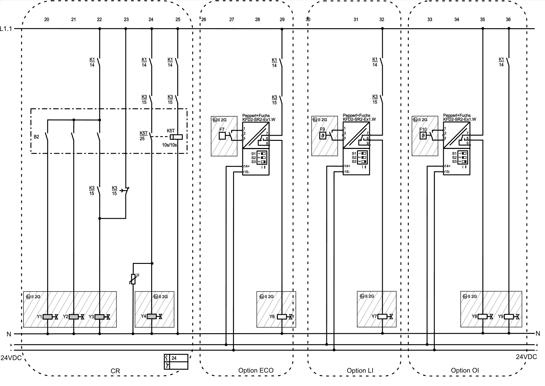
F7 | Cut-in delay "ECO" | |
F8-1 | Oil level switch (minimum oil level) | |
F8-2 | Oil level switch (maximum oil level) | |
F9 | Control thermostat "refrigerant injection" | |
F10 | Control thermostat for additional oil injection | |
F13 | Overload protective device | |
F17 | Control transformer fuse | |
F18 | Control circuit fuse for extra low voltage | |
H1 | Light "motor fault" (excess temperature/phase failure) | |
H2 | Light "start delay" | |
H4 H4-1 H4-2 | Light "oil level fault" | |
K1 | Contactor "1st part winding" (PW) or main contactor (star-delta) | |
K2 | Contactor "2nd part winding" (PW) or delta contactor (star-delta) | |
K3 | Star contactor (star-delta) | |
K4 | Auxiliary contactor | |
K2T | Time relay "pause time" 300 s | |
K3T | Time relay "part winding" 0.5 s or "star-delta" 1 s ,"star-delta" from CS.95: 1.5 .. 2 s | |
K4T | Time relay "oil level switch" 90 s | |
K5T | Time pulse relay "CR4" flashing function on / off 10 s | |
M1 | Compressor | |
Q1 | Main switch | |
R1 | Oil heater | |
R2 | Oil temperature sensor/discharge gas temperature sensor | |
R3..8 | Temperature sensor in the motor | |
S1 | Control switch (on/off) | |
S2 | Reset "motor and discharge gas temperatures" or "motor rotation direction" | |
T1 | Control transformer (example of 230 V, required according to EN60204-1) | |
U | Interference suppressor: Varistor or RC element, if required | |
Y1 | Solenoid valve "capacity regulator" CR1 | |
Y2 | Solenoid valve "capacity regulator" CR2 | |
Y3 | Solenoid valve "capacity regulator" CR3 | |
Y4 | Solenoid valve "capacity regulator" CR4 | |
Y5 | Solenoid valve "liquid line" | |
Y6 | Solenoid valve "ECO" | |
Y7 | Solenoid valve "refrigerant injection" | |
Y8 | Solenoid valve "additional oil injection" | |
Y9 | Solenoid valve "oil cooler line" | |
SE-* | Compressor protection device for motor and discharge gas temperatures ① |
① The SE-i1 basic sensor kit cannot perform the evaluation of the OLC, must not be provided with the retrofit kit, cannot be equipped with an optional temperature sensor and is not wired and tested ex factory.
Technical documents for further information:
- SB-179: Operating instructions Semi-hermetic compact screw compressors in special explosion-proof design