CS.65 .. 85 with SE-i1, PW start, stepless capacity control, full sensor kit
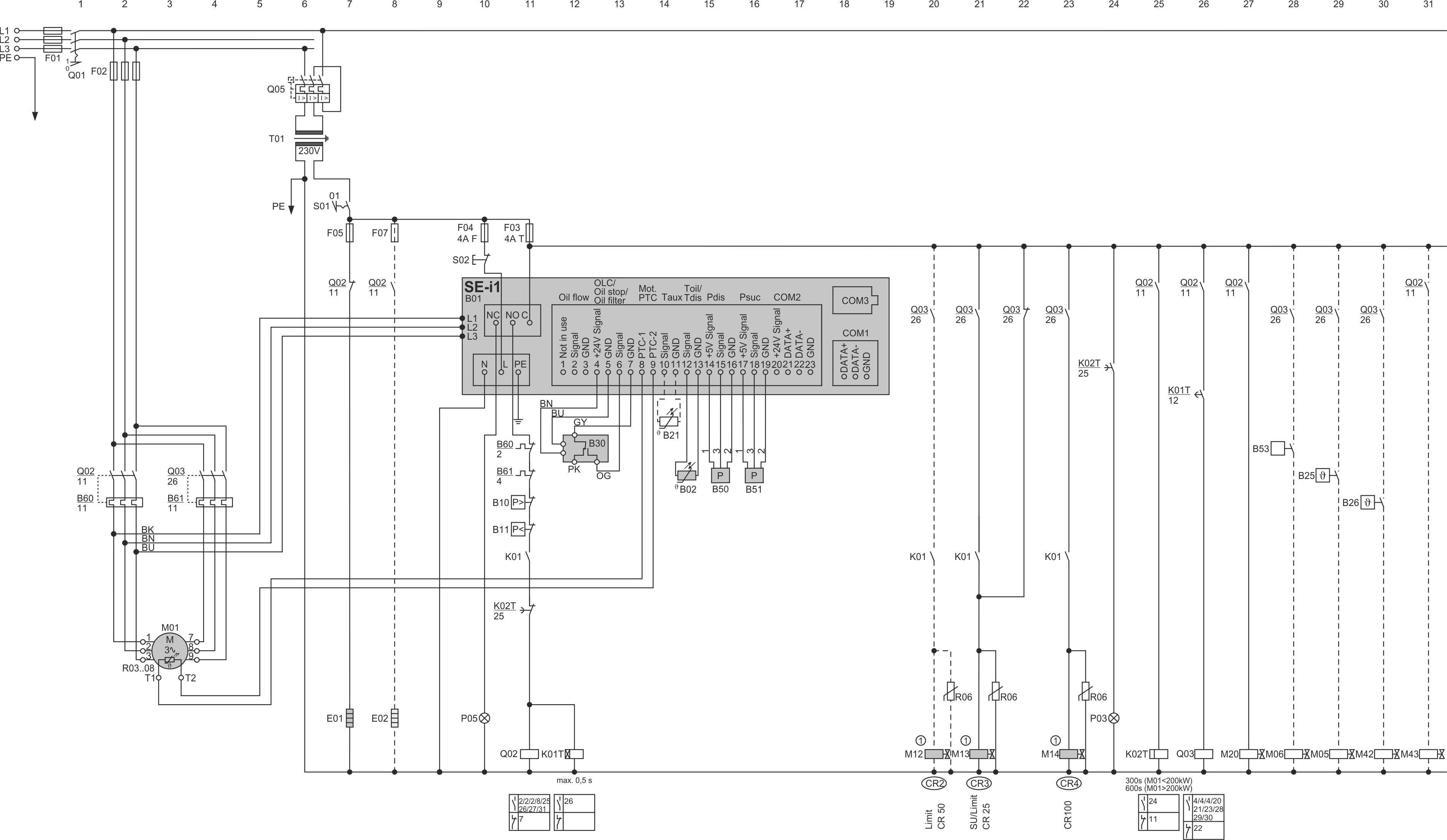
(1): Pulse time approx. 0.5 to max. 1 s, depending on system characteristics.
This schematic wiring diagram also applies to the corresponding CS.P models with R290 (propane).
Last revision of the diagram:
26.02.2026
Abbr. | Component |
|---|---|
B01 | Compressor protection device |
B02 | Discharge gas temperature sensor |
B03 .. 08 | Temperature sensors in motor windings |
B10 | High pressure switch |
B11 | Low pressure switch |
B16 | additional discharge gas temperature sensor |
B21 | Optional temperature sensor |
B25 | LI control thermostat |
B26 | Control thermostat for additonal oil injection, CSV.: for oil cooling |
B30 | Oil level switch |
B50 | High pressure transmitter |
B51 | Low pressure transmitter |
B53 | ECO switch-on |
B60 | Overload protective device |
B61 | Overload protective device for second part winding |
E01 | Oil heater |
E02 | Terminal box cover heater |
F01 | Main fuse |
F02 | Compressor fuse |
F03 | Control circuit fuse |
F04 | Fuse of compressor protection device or compressor module |
F05 | Fuse of oil heater |
F07 | Fuse of terminal box cover heater |
F08 | Fuse of rotation direction monitoring |
K01 | Superior controller |
K01T | Time relay for part winding start or for star-delta start |
K02T | Time relay for minimum shut-off period of compressor |
K06T | Time relay for capacity regulator |
K07T | Time relay for start unloading |
K10 | Auxiliary relay for status message of compressor |
K11 | Auxiliary relay for status message of compressor |
M01 | Compressor motor |
M05 | SV for liquid injection with LI, RI or CIC injection valve |
M06 | SV for economiser (ECO) |
M11 | SV for capacity regulator 1, CR1, CR+, CRII-2 or start unloading |
M12 | SV for capacity regulator 2, CR2, CR- or CRII-1 |
M13 | SV for capacity regulator 3, CR3 or CRII-3 |
M14 | SV for capacity regulator CR4 |
M20 | SV for liquid line |
M30 | Evaporator fan |
M42 | SV for additional oil injection |
M43 | SV for oil cooler line |
P03 | Light: time delay is active |
P05 | Light: compressor fault |
P11 | Light: FI fault |
Q01 | Main switch |
Q02 | Contactor for first part winding (PW) or main contactor (Y/Δ) or compressor contactor (DOL) |
Q03 | Contactor for second part winding (PW) or delta contactor (Y/Δ) |
Q04 | Star contactor (Y/Δ) |
Q05 | Control transformer fuse |
R06 | Interference suppressor (if required, e. g. from Murr Elektronik) |
S01 | Control switch (on-off) |
S02 | Reset of compressor safety chain |
T01 | Control transformer (example for 230 V, required according to EN60204-1) |
T02 | Frequency inverter (FI) |
T03 | Soft starter |
The cable colours are noted in accordance with IEC DIN60757.
Technical documents for further information: