ECOLITE LHG7EF (for R744)
Last revision of the diagram:
15.04.2026
Abbr. | Component |
|---|---|
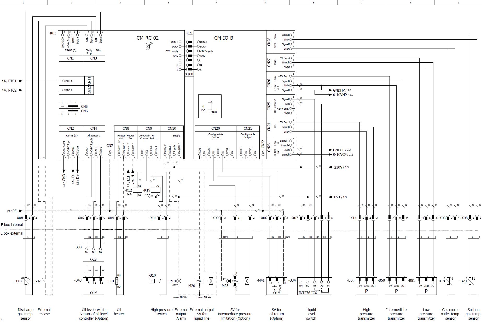
B02 | Discharge gas temperature sensor |
B10 | High pressure switch |
B18 | Gas cooler outlet temperature sensor |
B20 | Suction gas temperature sensor |
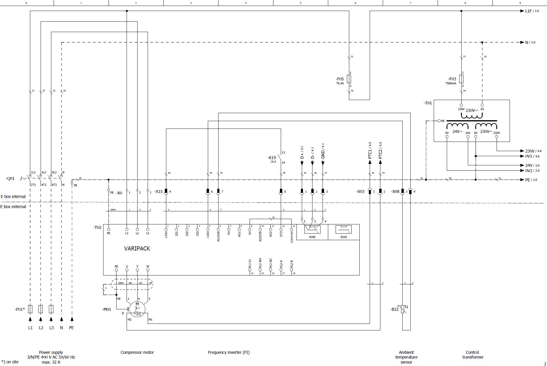
B22 | Ambient temperature sensor |
B30 | Oil level switch |
B34 | Liquid level switch |
B43 | Sensor of oil level controller |
B50 | High pressure transmitter |
B51 | Low pressure transmitter |
B58 | Intermediate pressure transmitter |
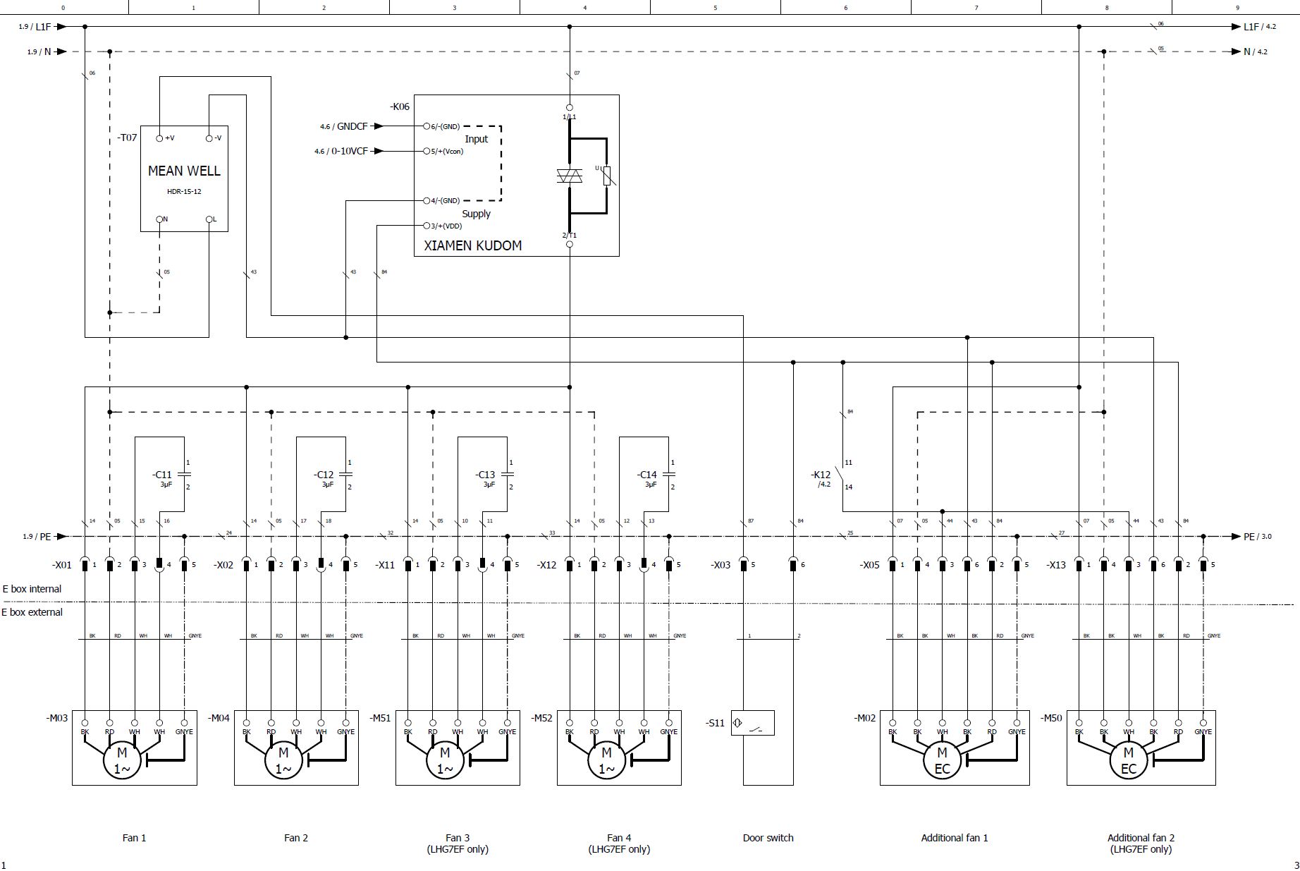
C11 | Run capacitor for fan 1 |
C12 | Run capacitor for fan 2 |
C13 | Run capacitor for fan 3 |
C14 | Run capacitor for fan 4 |
E01 | Oil heater |
F01 | Main fuse |
F03 | Control circuit fuse |
F05 | Fuse of oil heater |
K03 | Compressor module |
K06 | Fan(s) control module |
K12 | Auxiliary relay |
K19 | Auxiliary relay: safety chain enabled |
K21 | Extension board |
M01 | Compressor motor |
M02 | Additional fan |
M03 | Fan 1 |
M04 | Fan 2 |
M20 | SV for liquid line |
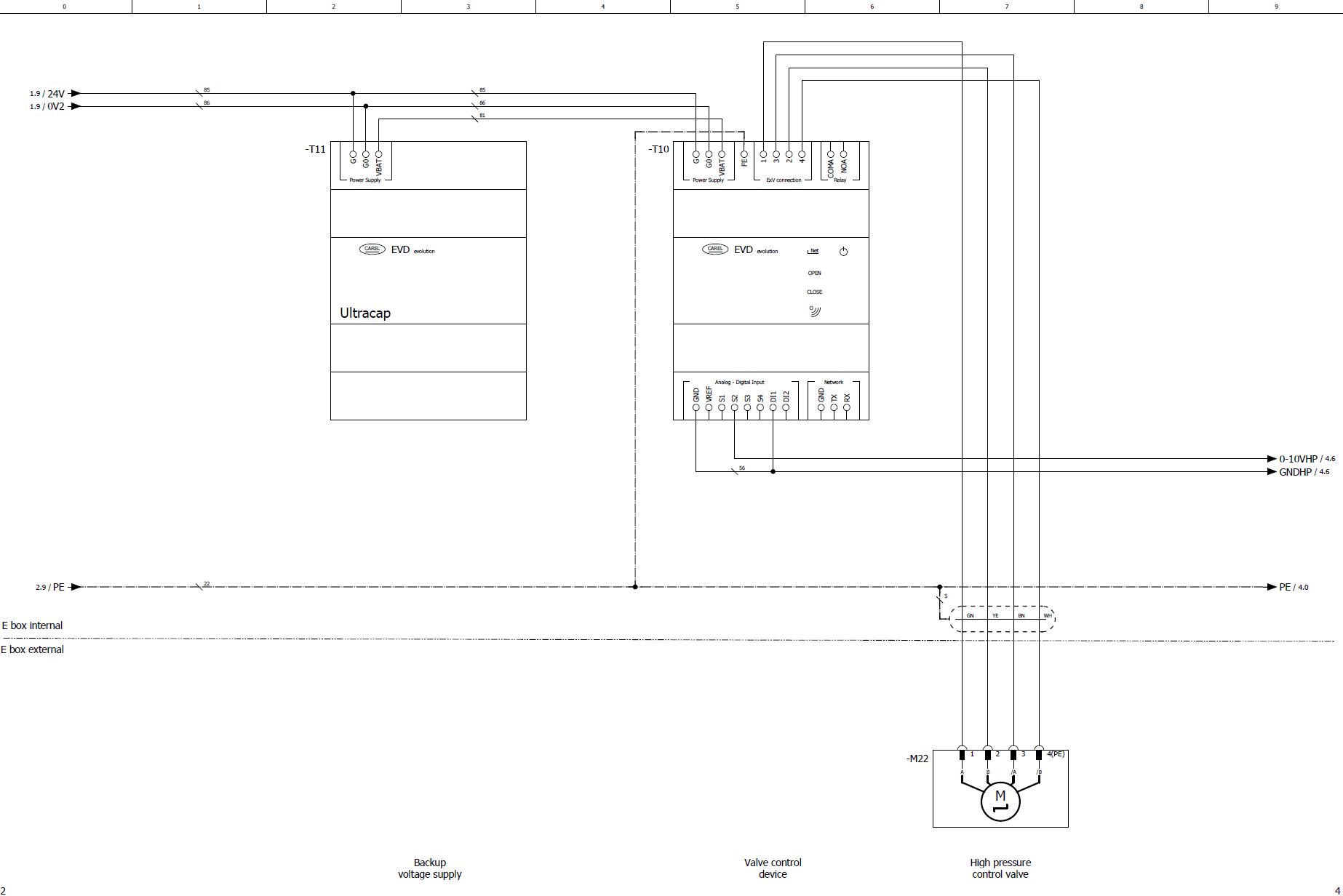
M22 | High pressure control valve |
M41 | SV for oil return |
M50 | Additional fan 2 |
M51 | Fan 3 |
M52 | Fan 4 |
P10 | Light: collective fault |
Q01 | Main switch |
S07 | External release |
S11 | Door switch |
T01 | Control transformer (example for 230 V, required according to EN60204-1) |
T02 | Frequency inverter (FI) |
T07 | Power supply device for auxiliary voltage |
T10 | Valve control device |
T11 | Backup voltage supply |
The cable colours are noted in accordance with IEC DIN60757.
Technical documents for further information:
- KB-207: Operating instructions ECOLITE - Air-cooled condensing units with R744