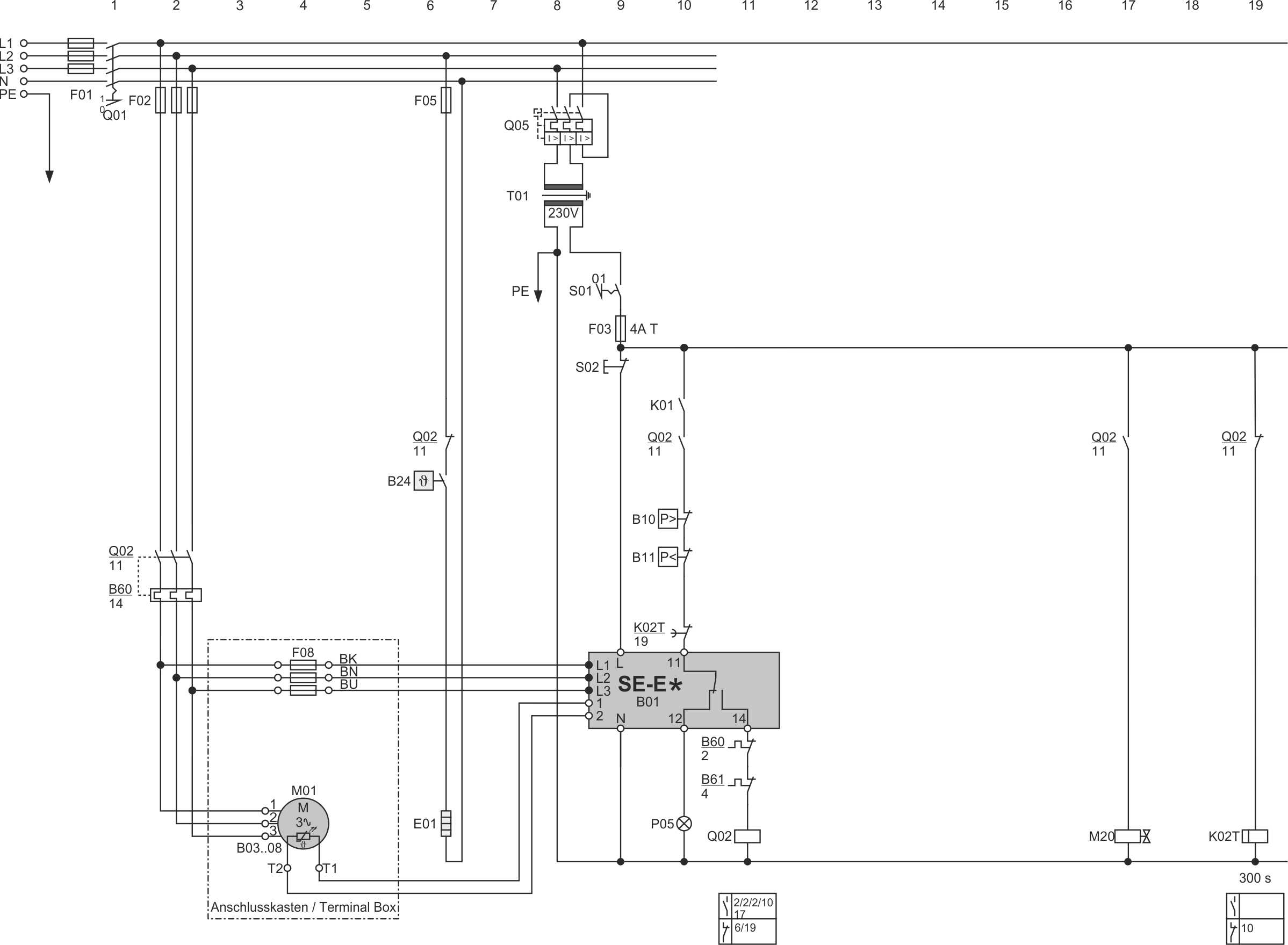
VSK31 with terminal box, SE-E*, direct-on-line start
Last revision of the diagram:
14.02.2025
Abbr. | Component |
|---|---|
B01 | Compressor protection device |
B02 | Discharge gas temperature sensor |
B03 .. 08 | Temperature sensors in motor windings |
B10 | High pressure switch |
B11 | Low pressure switch |
B24 | Oil thermostat |
B60 | Overload protective device |
B61 | Overload protective device for second part winding |
E01 | Oil heater |
F01 | Main fuse |
F02 | Compressor fuse |
F03 | Control circuit fuse |
F05 | Fuse of oil heater |
F08 | Fuse of rotation direction monitoring |
K01 | Superior controller |
K01T | Time relay for part winding start or for star-delta start |
K02T | Time relay for minimum shut-off period of compressor |
K10 | Auxiliary relay for status message of compressor |
K11 | Auxiliary relay for status message of compressor |
M01 | Compressor motor |
M11 | SV for capacity regulator 1, CR1, CR+, CRII-2 or start unloading |
M20 | SV for liquid line |
P05 | Light: compressor fault |
P11 | Light: FI fault |
Q01 | Main switch |
Q02 | Contactor for first part winding (PW) or main contactor (Y/Δ) or compressor contactor (DOL) |
Q03 | Contactor for second part winding (PW) or delta contactor (Y/Δ) |
Q04 | Star contactor (Y/Δ) |
Q05 | Control transformer fuse |
S01 | Control switch (on-off) |
S02 | Reset of compressor safety chain |
T01 | Control transformer (example for 230 V, required according to EN60204-1) |
T02 | Frequency inverter (FI) |
Technical documents for further information: