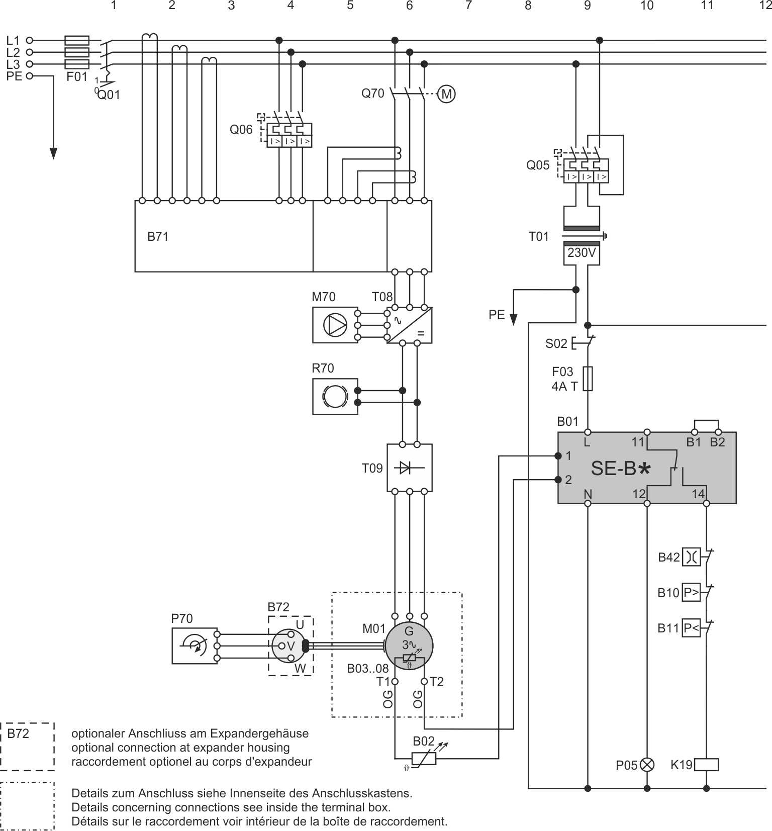
HSE.85 expander with SE-B*, generator operation
Last revision of the diagram:
08.11.2024
Abbr. | Component |
|---|---|
B01 | Compressor protection device |
B02 | Discharge gas temperature sensor |
B03 .. 08 | Temperature sensors in motor windings |
B10 | High pressure switch |
B11 | Low pressure switch |
B24 | Oil thermostat |
B71 | Mains monitoring device |
B72 | Speed sensor |
F01 | Main fuse |
F03 | Control circuit fuse |
K19 | Auxiliary relay: safety chain enabled |
M01 | Compressor motor |
M70 | Pump |
P05 | Light: compressor fault |
P70 | Speed measurement |
Q01 | Main switch |
Q05 | Control transformer fuse |
Q06 | Overload protective device |
Q70 | Motor operated power breaker |
R70 | Braking device |
S02 | Reset of compressor safety chain |
T01 | Control transformer (example for 230 V, required according to EN60204-1) |
T08 | Inverter |
T09 | Rectifier |
Technical documents for further information: